INSTRUCTIONS AND PARTS MANUAL CW-18 CIRCLE WELDER Please record your equipment identification information below for future reference. This information can be found on your machine nameplate. Model Number Serial Number Date of Purchase Whenever you request replacement parts or information on this equipment, always supply the information you have recorded above. LIT-CW18-IPM-0810 CYPRESS WELDING EQUIPMENT INC.
PROTECT YOURSELF AND OTHERS FROM SERIOUS INJURY OR DEATH. KEEP CHILDREN AWAY. BE SURE THAT ALL INSTALLATION, OPERATION, MAINTENANCE AND REPAIR PROCEDURES ARE PERFORMED ONLY BY QUALIFIED INDIVIDUALS. ELECTRIC SHOCK can kill. 1) The equipment is not waterproof. Using the unit in a wet environment may result in serious injury. Do not touch equipment when wet or standing in a wet location. 2) The unused connectors have power on them.
HIGH FREQUENCY WARNINGS SPECIAL PRECAUTIONS ARE REQUIRED WHEN USING PLASMA, TIG OR ANY WELDING PROCESS THAT USES HIGH FREQUENCY TO STRIKE AN ARC. WARNING: HIGH FREQUENCY CAN EFFECT MACHINE OPERATION AND THEREFORE, WELD QUALITY. Read the precautions below before installing and using the equipment. PRECAUTIONS: 1) Some plasma or welding cables are strong sources of high frequency interference. NEVER lay a plasma or welding cable across the controls of the machine.
CW-18 CIRCLE WELDER INSTRUCTIONS AND PARTS MANUAL TABLE OF CONTENTS PAGE 6......... Introduction / Set-up and Operation 8......... LDC-NA3S NA-3 Wire Feeder Controls 10........ CWO-6210-CW18 Rotation Controls 11........ Technical Data / Dimensions 12........ CWO-1800 CW-18 Circle Welder / Parts List 13........ CWO-1800 CW-18 Circle Welder / Exploded View 14........ CWO-1800 CW-18 Circle Welder / Wiring Diagram / Electrical Component Chart 15........ CWO-3133 CW-11/CW-18 Collector with Power Racker 16.....
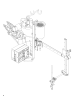
INTRODUCTION The CW-18 (CWO-1800) Circle Welder is designed for welding of nozzles into vessels or domed heads utilizing SUB-ARC, MIG or FLUX CORED PROCESS, with gas shielding. The CW-18 mounts on a 3-Jaw Chuck welding diameter 6” to 50” O.D. Features: • • • • • • • • • • • • • • Wire feeder with one set of drive rolls. 1/12 HP P.M. motor and rotational speed control. 600 AMP gun & cable assembly. Internal to NA3 50 ft. (15 m) power cable. 50 ft. (15 m) gas shielding hose. 50 ft. (15 m) weld cable.
SET-UP AND OPERATION CONTINUED: WIRE SPEED AND VOLTAGE ADJUSTMENT: The wire speed control on the front of the LDC-NA3S Wire Feed Control box has a dial that is calibrated directly in inches per minute. Set the voltage using the control on the power source. RISE AND FALL OF THE CAM: All circle welders are equipped with a rise and fall cam assembly. The cam assembly must be aligned before any other settings can be made.
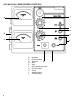
LDC-NA3S NA-3 WIRE FEEDER CONTROLS J A I H B G C F A. B. C. D. E. F. G. H. I. J.
LDC-NA3S NA-3 WIRE FEEDER CONTROLS, CONT’D. NOTE: For further information refer to Lincoln Electric NA-3 Operator’s Manual. A. AMMETER Indicates current only while welding. B. CIRCUIT BREAKER Protects the circuit from sever wire feed motor overload and short circuits. Press to reset. Locate and correct the cause for overload. C. VOLTMETER (Standard) Indicated welding voltage only while welding. Also indicates OCV below 60 volts. D. START Push-button beings the welding cycle E.
CWO-6210-CW18 ROTATION CONTROLS Speed Control Travel Direction On/Off Switch Pilot Light SPEED CONTROL: Controls the speed in which the machine travels. The depicted lines 0 to 100 should not be construed as inches per minute of travel. They should be considered as reference points only. TRAVEL DIRECTION: Controls the direction in which the machine will travel. Select forward for clockwise rotation, brake for stop, and reverse for counterclockwise rotation.
TECHNICAL DATA Input Voltage: Amperage: Voltage: Wire Sizes: Rotation Speed: Cam Range: Welding Radius: Shielding Gas: Height: Net Weight: Shipping Weight: 0-600 amps 115 VAC 0-50 1/16’’-7/32’’ (1.6-5.6 mm) .06-.72 rpm 0’’-7’’ (0-175 mm) 0’’-25” (0-635 mm) Solenoid Control 43’’ (1092 mm) 360 lbs. (163.6 kg) 490 lbs. (222.3 kg) DIMENSIONS: 70” (1778 mm) 36” (914 mm) 43” (1092 mm) 36.
CWO-1800 CW-18 CIRCLE WELDER / PARTS LIST ITEM 1 2 3 4 5 6 7 8 9 10 11 12 13 14 15 16 17 18 19 20 21 22 23 24 25 26 27 28 29 30 31 32 33 34 35 36 37 38 QTY 1 1 1 1 1 1 1 1 1 1 1 1 1 1 1 1 1 1 1 1 1 2 1 1 1 1 1 1 1 1 1 1 1 1 1 1 1 1 12 PART NUMBER CWO-1123 CWO-1124 CWO-1690 CWO-1811 CWO-1812 CWO-1813 CWO-1814 CWO-3133 CWO-1816 CWO-3931 CWO-1840 CWO-2020 CWO-3165 CWO-3205-11 CWO-3218 CWO-3312 CWO-3313 CWO-3359 CWO-3432 CWO-3498-11 CWO-3506 CWO-3528 CWO-3531 CWO-3534 CWO-3537 CWO-3538 CWO-3690-5/32 C
CWO-1800 CW-18 CIRCLE WELDER / EXPLODED VIEW 15 16 25 12 34 33 21 37 8 18 32 10 14 26 31 23 17 22 20 3 36 7 6 13 9 24 1 29 22 38 2 5 28 35 12 4 12 19 27 30 13
CWO-1800 CW-18 CIRCLE WELDER / WIRING DIAGRAM / ELECTRICAL COMPONENT CHART 1 4 13 5 9 14 10 8 7 3 6 11 12 ELECTRICAL COMPONENT CHART 14 ITEM 1 2 3 4 5 6 7 8 9 10 11 12 13 14 DESCRIPTION NA-3 Wire Feeder Weld Cable 4/0 50’ Collector for CW-11/CW-18 Brush Holder Support 4006 Motor Assy. NA-3 Wire Feeder Control Small Retainer Brush Terminal Block Assy.
CWO-3133 CW-11/CW-18 COLLECTOR WITH POWER RACKER 2 6 14, 21 3 10 4 9, 18, 22 5 19 15 12, 16 (4X) 1 7 8 13, 17 (4X) 23 11 15 ITEM QTY 1 1 2 12 3 1 4 13 5 1 6 1 7 1 8 1 9 2 10 1 11 1 12 4 13 4 14 1 15 4 16 4 17 4 18 2 19 1 20 1 21 1 22 2 23 140’’ PART NUMBER DESCRIPTION BUG-1034 PANEL CONNECTOR 4-T, M CWO-3127 BRASS RING 4.250’’ DIA X .188’’ THK CWO-5739 BRASS RING 4.250’’ DIA X 3.
CWO-1840 CW-18 RACKING SYSTEM / EXPLODED VIEW / PARTS LIST 2 1 ITEM QTY PART NUMBER DESCRIPTION 1 1 ABR-1050 V-GUIDE WAYS 40” 2 1 ABR-1060 V-GUIDE WAYS 33” 3 1 CWO-1675 VERTICAL RACKER 4 1 CWO-1695 ATTACHMENT BLOCK 5 1 CWO-3023-S TORCH ANGLE ADJUSTER 6 1 CWO-3460 33# LOAD SPRING ASSY.
CWO-3165 CW-18 HOUSING ASSEMBLY / EXPLODED VIEW / PARTS LIST 8 1 4 5 3 7 2 6 5 8 ITEM QTY PART NUMBER DESCRIPTION 1 1 CWO-4133 1/4-18 NPSM HEX PLUG, BRASS 2 1 CWO-5842 CENTER TUBE HOUSING, CW-18 3 1 CWO-5845 TOP HOUSING PLATE, CW-18 4 1 CWO-5853 LOWER HOUSING PLATE, CW-18 5 2 CWO-5980 PLASTIC BUSHING 6 3 CWO-9339 ANGLE FOR GUARD 7 3 FAS-0535 SOC HD CAP SCR 10-24 X 1/2” 8 8 FAS-0548 SOC HD CAP SCR 10-32 X 3/4” LOW HEAD CWO-3205-11 7" CAM ASSEMBLY / EXPLODED VIEW / PARTS LIST ITEM
CWO-3313 BRUSH HOLDER & SUPPORT ASSEMBLY / EXPLODED VIEW / PARTS LIST 2 10 2 9 8 2 11 12 1 1 4 1 3 6 13 7 12 5 5 ITEM QTY 1 3 2 6 3 1 4 5 6 7 8 9 10 11 12 13 1 2 1 1 1 4 1 4 3 3 PART NUMBER CWO-4046 CWO-4337 CWO-4472 DESCRIPTION LARGE BRUSH HOLDER LARGE BRUSH 1-1/2” X 3/4” X 2” BRUSH HOLDER SUPPORT CW-18 CWO-4473 CWO-5548 CWO-5549 FAS-0305 FAS-0309 FAS-0357 FAS-3304 WAS-0243 WAS-0280 WAS-0281 ATTACHMENT BAR CW-18 MICARTA SPACER MICARTA BUSHING HEX HD CAP SCR 1/2-13 X 2” HEX HD CAP SCR 1/2-13
CWO-3432 CW-18 SHAFT ASSEMBLY / EXPLODED VIEW / PARTS LIST 1 2 ITEM 1 2 3 QTY 1 2 1 PART NUMBER BUG-9096 CWO-4507 CWO-5779 2 3 DESCRIPTION OUTLET BUSHING, OXYGEN O-RING, OXYGEN, GAS SHAFT CW-18 CWO-3490 FLUX HOPPER ASSEMBLY / EXPLODED VIEW / PARTS LIST ITEM 1 2 3 4 5 N/S QTY 1 1 1 1 1 1 PART NUMBER CWO-3757 CWO-3760 CWO-3478 CWO-3769 GOF-3019 CWO-3491-48 DESCRIPTION HOPPER SUPPORT ROD CLAMP BLOCK 1/2” 1-3/4” HOSE BARB FLUX HOPPER STEEL 12” HANDLE W/ BOLTS FLUX HOSE 3/4” ID X 1” OD X 48” LG 5
CWO-3498-11 WIRE REEL ASSEMBLY / EXPLODED VIEW / PARTS LIST 1 ITEM 1 2 18 3 4 5 QTY 1 1 PART NUMBER DESCRIPTION BUG-3293 REEL, 60 LBS.
CWO-3528 2” FLANGE BEARING w/FASTENERS / EXPLODED VIEW / PARTS LIST ITEM 1 2 3 4 5 6 2 5 6 1 QTY 1 1 2 2 2 2 PART NUMBER CWO-1511 CWO-4482 FAS-1398 FAS-3305 WAS-0290 WAS-0291 DESCRIPTION 1/8” PIPE PLUG BLACK IRON FLANGE BEARING 2” BORE 9/16-12 HEX NUT HEX HD CAP SCR 9/16-12 X 2” 9/16” SAE WASHER 9/16” SPLIT LOCK WASHER 3 CWO-3531 MOTOR & TRANSMISSION PLATE ASSEMBLY / EXPLODED VIEW / PARTS LIST ITEM 1 2 3 4 5 6 7 8 9 10 11 12 13 QTY 1 1 1 1 5 8 3 2 4 5 5 4 8 PART NUMBER BUG-1338 CWO-5788 CWO-588
CWO-3534 SLIDE BAR ASSEMBLY / EXPLODED VIEW / PARTS LIST ITEM QTY 1 1 2 2 PLATE 3 2 4 4 1-1/4” 5 4 6 2 4 PART NUMBER DESCRIPTION CWO-3912 SLIDE BAR ASSEMBLY CWO-9033 TOP / BOTTOM VERTICAL SLIDE FAS-0399 FAS-2372 HEX HD CAP SCR 3/8-16 X 1” HEX HD CAP SCR 5/16-18 X WAS-0251 WAS-0262 5/16” SPLIT LOCKWASHER 3/8” SPLIT LOCKWASHER 5 1 2 6 2 3 CWO-3537 GUARD ASSEMBLY CW-18 / EXPLODED VIEW / PARTS LIST 1 3 5 ITEM 1 18 2 3 4 5 2 4 22 QTY PART NUMBER DESCRIPTION 1 CWO-5094 UPPER GUARD CB-2, C
CWO-3538 CW-18 CAMSHAFT & SPACER ASSEMBLY / EXPLODED VIEW / PARTS LIST 8 1 7 9 3 4 6 5 2 9 9 ITEM 1 2 3 4 5 6 7 8 9 QTY 1 1 1 1 1 2 1 1 3 PART # CWO-4352 CWO-5042 CWO-9081 CWO-9353 FAS-0399 FAS-1395 FAS-1396 FAS-2396 WAS-0260 DESCRIPTION BALL JOINT END 3/8-16 R.H. BALL JOINT END 3/8-16 L.H.
CWO-3931 SMALL BRUSH ASSEMBLY / EXPLODED VIEW / PARTS LIST 1 ITEM 1 2 3 4 5 6 18 7 8 9 10 11 12 1 7 QTY 1 12 12 12 12 1 PART NUMBER CWO-3947 CWO-5831 CWO-5874 CWO-5875 CWO-5876 CWO-9067 DESCRIPTION 12 POSITION SMALL BRUSH ASSY 1/8” x 1/8” x 1/8” BRUSH 1/8” BRUSH HOLDER CAP CLIP SMALL BRUSH RETAINER BLOCK, CW- 1 2 1 12 1 1 CWO-9082 FAS-0359 FAS-0593 TERM-WTE-1508 WAS-0260 WAS-0262 RETAINER SUPPORT SOC HD CAP SCR 10-24 X 1” SOC HD CAP SCR 3/8-16 X 1-1/2” #8 FORK, BLUE 3/8” SAE WASHER 3/8” SPLIT LOCKWA
CWO-3971 CONTROL CABLE / DETAIL VIEW / PARTS LIST ITEM 1 2 3 QTY 600” 1 1 4 9 PART NUMBER 900-4-016 BUG-5552-B BUG-6069-P DESCRIPTION 16/10 SO CABLE CABLE CLAMP CABLE CONNECTOR 9-T, F TERM-WTE-0602 #6 FORK, BLUE CWO-2978 FEEDER CONTROL BOX CABLE / DETAIL VIEW / PARTS LIST ITEM 1 2 3 4 QTY 32” 1 1 9 PART NUMBER 900-4-016 BUG-5552-B BUG-6069-P TERM-WTE-0602 DESCRIPTION 16/10 SO CABLE CABLE CLAMP CABLE CONNECTOR 9-T, F #6 FORK, BLUE 25
CWO-3974 33# LOAD SPRING ASSEMBLY / EXPLODED VIEW / PARTS 2 1 3 8 2 1 3 6 8 5 9 4 7 10 ITEM QTY 1 2 3 4 5 6 7 8 9 10 26 2 2 2 1 1 2 1 2 1 1 PART # CWO-4074 CWO-5707 CWO-5773 CWO-9230 FAS-0357 FAS-0555 FAS-1351 FAS-2697 WAS-0240 WAS-0243 DESCRIPTION SPRING 16.
CWO-6210-CW18 ROTATION CONTROL / EXPLODED VIEW / PARTS LIST 3 2 13 13,14,21 23 20 (x3) 22 12 6 (x2) 15, 17 21, 14, 13 14 11 24 15, 16 21 7 21 19 (x10) 29 13 8 29 14 27 10 4 18 1 ITEM QTY PART NUMBER 1 1 ARM-2279 2 1 BUG-9445 3 1 CON-PS04M 4 1 BUG-9687 5 1 BUG-9694 6 2 CSR-WTE-1597 7 1 CWO-6216 8 1 CWO-5547B 9 1 CWO-6206 10 1 CWO-6527 11 1 CWO-6839 12 1 CWO-6802 13 6 FAS-0115 14 6 FAS-1310 15 2 FHO-0188 16 1 MPD-1026 17 1 FUS-0257 18 1 MUG-1258-1 19 10 SCW-WTE-0264 20 3 TERM-WTE-0197 21
CWO-6210-CW18 ROTATION CONTROL / WIRING DIAGRAM / ELECTRICAL COMPONENT CHART 3 6 2 5 1 4 = INDICATES ITEMS THAT ARE SUPPLIED TOGETHER.
CWO-3690-_ K231 SUB ARC GUN 2 3 4 5 1 6 11A 11 7 ITEM QTY 1 1 2 1 3 1 4 1 13 5 1 6 1 *7 1 SIZE*) 8 1 9 1 10 1 11 1 11A 1 12 1 13 1 14 1 15 1 PART # PXS-15106-3/32 PXT-10570 PXS-10493-1 PXS-121312 DESCRIPTION NOZZLE INSERT SOCKET HEAD SCREW NOZZLE INSULATOR HEX HD SCR 1 1/2’’ & NUT 1/2’’- PXT-9967-10 CWO-8052 PXS-10125-_ NOZZLE BODY ROLL PIN NOZZLE BODY CONTACT TIP (SPECIFY WIRE PXS-10138 PXT-9078-1 PXT-9967-30 PXT-13835 PXT-3835-IN BUG-3161-P BUG-3163 BUG-3164 BUG-3165 FLUX CONE PLUG (INSULAT
CWO-3710-_ SUB ARC GUN ASSEMBLY ITEM QTY PART # 1 1 CWO-1816 2 2 CWO-1817 3 1 CWO-3697 4 1 CWO-3695-1/2 5 1 CWO-3970-72 6 1 CWO-3690-1/8 1 CWO-3690-3/16 1 CWO-3690-5/32 7 1 CWO-3491-48 8 1 FAS-0452 9* 1 BUG-2708 1 2 3 7 2 8 6 30 *Item not shown in drawing.
3-JAW EXPANDABLE CHUCKS 3-Jaw Expandable Chucks Mounts and automatically centers the Circle Welder on nozzles with or without flanges. As shown below. CWO-3660 PART NUMBER CWO-3660 CWO-3661 CWO-3362 CWO-3663 FOR NOZZLE I.D.’S 2”-8” (51-204 mm) 8”-16” (204-405 mm) 10”-24” (255-610 mm) 16”-42” (406-1065 mm) WEIGHT 68 lbs. (31 kg) 36 lbs. (16 kg) 51 lbs. (23 kg) 64 lbs.
OPTIONAL MOTORIZED RACKING EQUIPMENT / CWO-1640-M / EXPLODED VIEW / PARTS LIST 2 1 3 4 6 ITEM QTY 1 1 2 1 3 1 4 1 5 1 6 1 PART # ABR-1050-MH ABR-1060-MV CWO-1675-MV CWO-1695 CWO-3023-1 CWO-3460 DESCRIPTION MOTORIZED HORIZONTAL V-GUIDE WAYS 40” MOTORIZED VERTICAL V-GUIDE WAYS 33” MOTORIZED VERTICAL RACKER ATTACHMENT BLOCK TORCH ANGLE ADJUSTER 16” 33# LOAD SPRING ASSEMBLY 5 OPTIONAL MOTORIZED RACKING EQUIPMENT / CWP-3363 / EXPLODED VIEW / PARTS LIST 2 3 2 ITEM QTY 1 1 2 4 3 4 3 1 2 3 3 32 2 PART
OPTIONAL RACKING MOTORIZED RACKING/ CWP-3351 / EXPLODED VIEW / PARTS LIST 2 11 12 13 3 4 1 10 21 8 20 19 18 16 17 6 5 7 11 13, 11 8 15 16 ITEM QTY PART NUMBER 1 1 CWP-3355 2 1 CWO-5933 3 2 CWO-5565 4 1 CWP-3354 5 1 CWP-3353 6 2 CWP-3362 7 1 CWO-3865 8 5 CWO-9038 9 2 CWO-9065 10 1 CWP-3356 11 6 FAS-1301 12 2 WAS-0281 13 4 WAS-0280 14 4 FAS-2591-SS 15 4 FAS-1444-SS 16 10 FAS-0359-SS 17 1 FAS-0399 18 1 WAS-0262 19 1 WAS-0260 20 4 FAS-0555 21 4 WAS-0243 9 14 DESCRIPTION Hvy Duty Rack 150:1 No Mount
OPTIONAL MOTORIZED RACKING EQUIPMENT/ PRS-1075 / EXPLODED VIEW / PARTS LIST 34
OPTIONAL MOTORIZED RACKING EQUIPMENT/ PRS-1100/ EXPLODED VIEW / PARTS LIST ITEM 1 2 3 4 5 6 7 8 9 10 11 12 13 14 15 16 17 18 19 20 21 22 23 24 N/S Component Item PRS-1111 BUG-2923 BUG-2952 BUG-2933 BUG-2924 BUG-5001 BUG-5002 BUG-5003 PRS-1110 PRS-1112 MUG-1156 BUG-1404 BUG-1411 BUG-1384 BUG-1383 BUG-1551 BUG-9636 BUG-9902 CAS-1770 BUG-9446 BUG-9445 GOF-3115 BUG-9628 FAS-0124 FAS-1320 WAS-0221 SCW WTE 0514 FAS-0204 FAS-1305 WAS-0201 FAS-0112 SFX-1292 Description 120vac 240vac INPUT EN
OPTIONAL MOTORIZED RACKING EQUIPMENT/ PRS-1091-WD WIRING DIAGRAM/ PARTS LIST 36
PREVENTIVE MAINTENANCE / CW-18 CIRCLE WELDER IMPORTANT: Make sure the input power at the power source is turned off and the 50’ weld cable is disconnected from the circle welder prior to working inside the circle welder. AFTER DAILY USE: Refer to CW-18 Exploded View Parts List. (Pg. 12) Large Horizontal Racker Item #3: Inspect wheels and remove all dirt, grease, weld spatter and rust. Adjust wheels for snug fit and smooth operation.
PREVENTIVE MAINTENANCE / CW-18 CIRCLE WELDER, CONT’D. Refer to CW-18 Electrical Component Chart. (Pg. 14) NA-3 Wire Feeder Assembly Item #1: Check brushes for wear. Brushes should be replaced when their length is less than 1/4 inch. Replace strain relief on wire if pulled out of motor housing. Brush Holder & Support Item #4: Inspect brush holder. Make sure constant tension is being applied on the brushes. Brushes should move freely within the brush holder. Check brushes for arc build-up.
PREVENTIVE MAINTENANCE / CW-18 CIRCLE WELDER, CONT’D. Refer to CW-18 Electrical Component Chart. (Pg. 14) CW-18 Collector Item #3: The collector ring should be sanded once a year. If the collector ring is pitted too badly it should be replaced. Inspect all wires coming out of the collector ring for cut or missing insulation. All wires should be fastened to the center shaft with a nylon cable tie. Tighten four set screws if needed.
WARRANTY Limited 3-Year Warranty Model ______________________________ Serial No. ___________________________ Date Purchased: _____________________ Where Purchased:___________________ For a period ending one (1) year from the date of invoice, Manufacturer warrants that any new machine or part is free from defects in materials and workmanship and Manufacturer agrees to repair or replace at its option, any defective part or machine.