
Specifications


STK17TA8
Document #: 001-52039 Rev. *C Page 16 of 24
Calibrating The Clock
The RTC is driven by a quartz controlled oscillator with a nominal
frequency of 32.768 KHz. Clock accuracy will depend on the
quality of the crystal, specified (usually 35 ppm at 25 C). This
error could equate to 1.53 minutes gain or loss per month. The
STK17TA8 employs a calibration circuit that can improve the
accuracy to +1/-2 ppm at 25 C. The calibration circuit adds or
subtracts counts from the oscillator divider circuit.
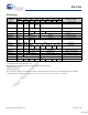
The number of time pulses are added or substracted depends
upon the value loaded into the five calibration bits found in
Calibration register (at 0x1FFF8). Adding counts speeds the
clock up; subtracting counts slows the clock down. The
Calibration bits occupy the five lower order bits of the register.
These bits can be set to represent any value between 0 and 31
in binary form. Bit D5 is a Sign bit, where a “1” indicates positive
calibration and a “0” indicates negative calibration. Calibration
occurs during a 64 minute period. The first 62 minutes in the
cycle may, once per minute, have one second either shortened
by 128 or lengthened by 256 oscillator cycles.
If a binary “1” is loaded into the register, only the first 2 minutes
of the 64 minute cycle is modified; if a binary 6 is loaded, the first
12 will be affected, and so on. Therefore each calibration step
has the effect of adding 512 or subtracting 256 oscillator cycles
for every 125,829,120 actual oscillator cycles. That is +4.068 or
-2.034 ppm of adjustment per calibration step in the calibration
register.
The calibration register value is determined during system test
by setting the CAL bit in the Flags register (at 0x1FFF0) to 1. This
causes the INT pin to toggle at a nominal 512 Hz. This frequency
can be measured with a frequency counter. Any deviation
measured from the 512 Hz will indicate the degree and direction
of the required correction. For example, a reading of 512.01024
Hz would indicate a +20 ppm error, requiring a -10 (001010) to
be loaded into the Calibration register. Note that setting or
changing the calibration register does not affect the frequency
test output frequency.
To set or clear CAL, set the write bit “W” (in the Flags register at
0x1FFF0) to a "1" to enable writes to the Flag register. Write a
value to CAL. and then reset the write bit to "0" to disable writes.
The default Calibration register value from the factory is 00h. The
user calibration value loaded is retained during a power loss.
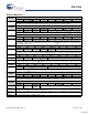
Alarm
The alarm function compares a user-programmable alarm
time/date (stored in registers 0x1FFF1-5) with the real time clock
time-of-day/date values. When a match occurs, the alarm flag
(AF) is set and an interrupt is generated if the alarm interrupt is
enabled. The alarm flag is automatically reset when the Flags
register is read.
Each of the alarm registers has a match bit as its MSB. Setting
the match bit to a 1 disables this alarm register from the alarm
comparison. When the match bit is 0, the alarm register is
compared with the equivalent real time clock register. Using the
match bits, the alarm can occur as specifically as one particular
second on one day of the month or as frequently as once per
minute.
Note The product requires the match bit for seconds(1x1FFF2 -
D7) be set to 0 for proper operation of the Alarm Flag and
Interrupt.
The alarm value should be initialized on power up by software
since the alarm registers are not nonvolatile.
To set or clear Alarm registers, set the write bit “W” (in the Flags
register at 0x1FFF0) to a "1" to enable writes to the Alarm
registers. Write an alarm value to the alarm registers and then
reset the write bit to "0" to disable writes.
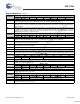
Watchdog Timer
The watchdog timer is designed to interrupt or reset the
processor should the program get hung in a loop and not
respond in a timely manner. The software must reload the
watchdog timer before it counts down to zero to prevent this
interrupt or reset.
The watchdog timer is a free running down counter that uses the
32 Hz clock (31.25 ms) derived from the crystal oscillator. The
watchdog timer function does no operate unless the oscillator is
running.
The watchdog counter is loaded with a starting value from the
load register and then counts down to zero setting the watchdog
flag (WDF) and generating an interrupt if the watchdog interrupt
is enabled. The watchdog flag bit is reset when the flag register
is read. The operating software would normally reload the
counter by setting the watchdog strobe bit (WDS) to 1 within the
timing interval programmed into the load register.
To use the watchdog timer to reset the processor on timeout, the
INT is tied to processor master reset and Interrupt register is
programmed to 24h to enable interrupts to pulse the reset pin on
timeout.
To load the watch dog timer, set a new value into the load register
by writing a “0” to the watchdog write bit (WDW) of the watchdog
register (at 01x1FFF7). Then load a new value into the load
register. Once the new value is loaded, the watchdog write bit is
then set to 1 to disable watchdog writes. The watchdog strobe
bit (WDS) is then set to 1 to load this value into the watchdog
timer.
Note Setting the load register to zero disables the watchdog
timer function.
The system software should initialize the watchdog load register
on power up to the desired value since the register is not nonvol-
atile.
Power Monitor
The STK17TA8 provides a power monitor function. The power
monitor is based on an internal band-gap reference circuit that
compares the V
CC
voltage to V
SWITCH
.
When the power supply drops below V
SWITCH
, the real time clock
circuit is switched to the backup supply (battery or capacitor).
When operating from the backup source, no data may be read
or written to the nvSRAM and the clock functions are not
available to the user. The clock continues to operate in the
background. Updated clock data is available to the user t
HRECALL
delay after VCC has been restored to the device.
When power is lost, the PF flag in the Flags Register is set to
indicate the power failure and an interrupt is generated if the
power fail interrupt is enabled (interrupt register=20h). This line
would normally be tied to the processor master reset input for
perform power-off reset.
[+] Feedback
Not Recommended for New Designs