
Specifications


STK17TA8
Document #: 001-52039 Rev. *C Page 17 of 24
Interrupts
The STK17TA8 has a Flags register, Interrupt Register, and
interrupt logic that can interrupt a microcontroller or generate a
power up master reset signal. There are three potential interrupt
sources: the watchdog timer, the power monitor, and the clock
alarm. Each can be individually enabled to drive the INT pin by
setting the appropriate bit in the Interrupt register. In addition,
each has an associated flag bit in the Flags register that the host
processor can read to determine the interrupt source. Two bits in
the Interrupt register determine the operation of the INT pin
driver.
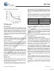
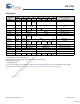
A functional diagram of the interrupt logic is shown below:
Figure 16. Interrupt Block Diagram
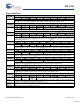
Interrupt Register
Watchdog Interrupt Enable (WIE). When set to 1, the watchdog
timer drives the INT pin when a watchdog time-out occurs. When
WIE is set to 0, the watchdog time-out only sets the WDF flag bit.
Alarm Interrupt Enable (AIE). When set to 1, the INT pin is driven
when an alarm match occurs. When set to 0, the alarm match
only sets the AF flag bit.
Power Fail Interrupt Enable (PFE). When set to 1, the INT pin is
driven by a power fail signal from the power monitor circuit. When
set to 0, only the PF flag is set.
High/Low (H/L). When set to a 1, the INT pin is active high and
the driver mode is push-pull. The INT pin can drive high only
when V
CC
>V
SWITCH
. When set to a 0, the INT pin is active low
and the drive mode is open-drain. The active low (open drain)
output is maintained even when power is lost.
Pulse/Level (P/L). When set to a 1, the INT pin is driven for
approximately 200 ms when an interrupt occurs. The pulse is
reset when the Flags register is read. When P/L is set to a 0, the
INT pin is driven high or low (determined by H/L) until the Flags
register is read.
The Interrupt register is loaded with the default value 00h at the
factory. The user should configure the Interrupt register to the
value desired for their desired mode of operation. Once
configured, the value is retained during power failures.
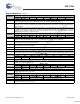
Flags Register
The Flags register has three flag bits: WDF, AF, and PF. These
flags are set by the watchdog time-out, alarm match, or power
fail monitor respectively. The processor can either poll this
register or enable interrupts to be informed when a flag is set.
The flags are automatically reset once the register is read.
The Flags register is automatically loaded with the value 00h on
power up (with the exception of the OSCF bit).
Watchdog
Timer
Power
Monitor
Clock
Alarm
PF
PFE
VINT
AIE
AF
P/L
H/L
Pin
Driver
INT
V
CC
WIE
WDF
V
SS
[+] Feedback
Not Recommended for New Designs