
1 Mbit nvSRAM Specification Sheet


PRELIMINARY
CY14B101Q1
CY14B101Q2
CY14B101Q3
Document #: 001-50091 Rev. *A Page 12 of 22
bit is cleared on the positive edge of CS
following the STORE
instruction.
Software RECALL
When a RECALL instruction is executed, nvSRAM performs a
Software RECALL operation. To issue this instruction, the device
must be write enabled (WEN = ‘1’).
The instruction is performed by transmitting the RECALL opcode
on the SI pin following the falling edge of CS
. The WEN bit is
cleared on the positive edge of CS
following the RECALL
instruction.
AutoStore Disable (ASDISB)
AutoStore is enabled by default in CY14B101Q2/CY14B101Q3.
The ASDISB instruction disables the AutoStore. This setting is
not nonvolatile and needs to be followed by a STORE sequence
to survive the power cycle.
To issue this instruction, the device must be write enabled (WEN
= ‘1’). The instruction is performed by transmitting the ASDISB
opcode on the SI pin following the falling edge of CS
. The WEN
bit is cleared on the positive edge of CS
following the ASDISB
instruction.
AutoStore Enable (ASENB)
The AutoStore Enable instruction enables the AutoStore on
CY14B101Q1. This setting is not nonvolatile and needs to be
followed by a STORE sequence to survive the power cycle.
To issue this instruction, the device must be write enabled (WEN
= ‘1’). The instruction is performed by transmitting the ASENB
opcode on the SI pin following the falling edge of CS. The WEN
bit is cleared on the positive edge of CS
following the ASENB
instruction.
Note If ASDISB and ASENB instructions are executed in
CY14B101Q1, the device is busy for the duration of software
sequence processing time (t
SS
). However, ASDISB and ASENB
instructions have no effect on CY14B101Q1 as AutoStore is
internally disabled.
HOLD Pin Operation
The HOLD pin is used to pause the serial communication. When
the device is selected and a serial sequence is underway, HOLD
is used to pause the serial communication with the master device
without resetting the ongoing serial sequence. To pause, the
HOLD
pin must be brought LOW when the SCK pin is LOW. To
resume serial communication, the HOLD
pin must be brought
HIGH when the SCK pin is LOW (SCK may toggle during HOLD
).
While the device serial communication is paused, inputs to the
SI pin are ignored and the SO pin is in the high impedance state.
This pin can be used by the master with the CS pin to pause the
serial communication by bringing the pin HOLD
LOW and
deselecting an SPI slave to establish communication with
another slave device, without the serial communication being
reset. The communication may be resumed at a later point by
selecting the device and setting the HOLD
pin HIGH.
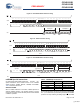
Figure 15. Software STORE Operation
Figure 16. Software RECALL Operation
Figure 17. AutoStore Disable Operation
0 0 1 1 1 1 0 0
CS
SCK
SI
SO
Hi-Z
0 1 2 3 4 5 6 7
0 1 1 0 0 0 0 0
CS
SCK
SI
0 1 2 3 4 5 6 7
SO
Hi-Z
0 0 0 1 1 0 0 1
CS
SCK
SI
SO
Hi-Z
0 1 2 3 4 5 6 7
Figure 18. AutoStore Enable Operation
Figure 19. HOLD Operation
0 1 0 1 1 0 0 1
CS
SCK
SI
SO
Hi-Z
0 1 2 3 4 5 6 7
~
~
~
~
CS
SCK
HOLD
SO
[+] Feedback