
User Guide


CY24713
Document #: 38-07396 Rev. *A Page 3 of 5
AC Electrical Characteristics (V
DD
= 3.3V)
Parameter
[3]
Description Conditions Min Typ. Max Unit
DC Output Duty Cycle Duty Cycle is defined in Figure 3 50% of V
DD
45 50 55 %
ER
0
Rising Edge Rate Output Clock Edge Rate, Measured from 20% to
80% of
V
DD,
C
LOAD
= 15 pF Figure 4.
0.8 1.4 – V/ns
EF
1
Falling Edge Rate Output Clock Edge Rate, Measured from 80% to
20% of
V
DD,
C
LOAD
= 15 pF Figure 4.
0.8 1.4 – V/ns
t
9
Clock Jitter Peak-Peak period jitter maximum absolute jitter – 200 250 ps
t
10
PLL Lock Time – – 3 ms
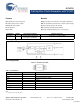
Figure 2. Test Circuit
0.1 μF
V
DD
CLK out
C
LOAD
GND
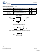
OUTPUTS
t1
t2
CLK
50%
50%
Figure 3. Duty Cycle Definition; DC = t2/t1
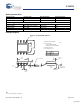
t3
CLK
80%
20%
t4
Figure 4. Rise and Fall Time Definitions: ER = 0.6 x V
DD
/t3, EF = 0.6 x V
DD
/t4
Note
3. Not 100% tested
[+] Feedback