CY3270 PSoC® FirstTouch™ Guide Document # 001-15945 Rev. ** Cypress Semiconductor 198 Champion Court San Jose, CA 95134-1709 Phone (USA): 800.858.1810 Phone (Intnl): 408.943.2600 http://www.cypress.
Copyrights Copyrights © Cypress Semiconductor Corporation, 2007. The information contained herein is subject to change without notice. Cypress Semiconductor Corporation assumes no responsibility for the use of any circuitry other than circuitry embodied in a Cypress product. Nor does it convey or imply any license under patent or other rights.
Contents 1. Introduction 1.1 1.2 Document History ........................................................................................................6 Document Conventions ...............................................................................................6 2. Getting Started 2.1 2.2 2.3 2.4 2.5 7 Install Hardware and Run the CapSense Touch Sensing Design ...............................7 Install Software ..................................................................................
Contents 4 CY3270 PSoC® FirstTouch™ Guide, Document # 001-15945 Rev.
1. Introduction The PSoC® FirstTouch™ Kit includes a USB interface dongle, referred to as the FTPC bridge, and a multifunction expansion card, referred to as the FTMF Expansion Card. The FTMF Expansion Card demonstrates a variety of applications using ‘PSoC Powered Peripherals’. The FTMF Expansion Card connects to the bridge through the bridge’s built-in 8x2 pin expansion port.
Introduction 1.1 Document History This section serves as a chronicle of the CY3270 PSoC® FirstTouch™ Guide. CY3270 PSoC® FirstTouch™ Guide History Release Date Firmware Revision Guide Version Originator 09/05/07 See Note a ** ARI a 1.2 Description of Change This guide is a new document. PSoC Express 3.0 generates the firmware. Document Conventions This guide uses the Courier New font to distinguish file location and source code examples from regular text.
2. 2.1 Getting Started Install Hardware and Run the CapSense Touch Sensing Design To install the kit hardware and run the CapSense touch sensing design, do as follows: 1. Remove both end caps from the FTPC Bridge and then connect the FTMF Expansion Card into the header of the FTPC Bridge such that ‘Cypress Perform’ is visible on both boards. Insert the assembled kit into your computer USB port. Select Cancel in the ‘Found New Hardware Wizard’ window that appears. 2.
Getting Started 3. From the top menu bar, click Build and then select Generate/Build {your project name} Project. Click Next in the following two screens. 4. From the top menu bar, click Program and then select Programmer. Within the Programmer window, select Port > FirstTouch and set the Programming Mode button to Reset. Select the File Load button. Within the ‘Open’ window, double-click {your project name}.hex located in {your project folder}\{your project name}\output under the default \..
Getting Started 2.4.1 CapSense Touch Sensing Demonstration (default) The pre-programmed CapSense Touch Sensing demonstration shows how to use the CapSense Touch Sensing slider to control LED color. Run your finger across the CapSense Touch Sensing slider (see Figure 2-1) and notice how the color of the LED color changes. The CY8C21434 PSoC that resides on the FTMF Expansion Card detects your finger’s position on the CapSense Touch Sensing slider and controls the LEDs output. Figure 2-2.
Getting Started 2.4.2 Temperature Sensing Demonstration The temperature sensing demonstration shows how to use a temperature sensor to control LED color. Follow the CapSense Touch Sensing based guidelines in section 2.5 Exploring the FTMF Expansion Card Demonstration Projects to simulate, build, and program the FTMF Expansion Board with the temperature sensing demonstration. Touch the temperature sensor (see Figure 2-1) and notice how the LED color changes.
Getting Started 2.4.3 Light Sensing Demonstration The light sensing demonstration shows how to use an ambient light sensor to control LED intensity. Follow the CapSense Touch Sensing based guidelines in section 2.5 Exploring the FTMF Expansion Card Demonstration Projects to simulate, build, and program the FTMF Expansion Board with the ambient light sensing demonstration. Cover the light sensor (see Figure 2-1 on page 8) with the palm of your hand and notice how the intensity of the LED changes.
Getting Started 2.4.4 CapSense Proximity Sensing Demonstration The CapSense proximity sensing demonstration shows how to use a proximity sensor to control LED color. The proximity detector requires the use of a Proximity Antenna and can sense an object with approximately 2–3 inches of range. In the FirstTouch Kit, this sense antenna is formed by attaching the provided wire into the pin socket labeled PRX1 as shown in Figure 2-1 on page 8.
Getting Started 2.5 Exploring the FTMF Expansion Card Demonstration Projects To explore the various FTMF Expansion Card projects, do as follows: 1. Remove the FTPC Bridge from the USB port on the PC. 2. Connect the FTMF Expansion Card into the header of the FTPC Bridge such that ‘Cypress Perform’ is visible on both the FTPC Bridge and the FTMF Expansion Card. 3. Once the two are properly connected, insert the complete FirstTouch Kit back into the USB port. 2.5.
Getting Started 2.5.3 Simulating the Project Simulation is a very useful tool. You can run the simulation on the project you defined; if the results are not what you expected, you can go and change the design until you get the results you want. This saves time and effort by allowing evaluation of your design's operation prior to programming the hardware.
Getting Started 2.5.6 Verifying the Results Once the programming completes successfully, the FTPC Bridge resets the FTMF Expansion Card and begins running your project on the FTMF Expansion Card. Verify the project as follows: Did the changes that were made take effect? If not, return to the PSoC Express Design Editor, make any necessary changes, and reprogram your FTMF Expansion Card again. 2.5.
Getting Started 16 CY3270 PSoC® FirstTouch™ Guide, Document # 001-15945 Rev.
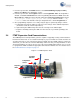
3. Technical Reference 3.1 FTPC Bridge Details The FTPC Bridge is the interface bridge between the expansion cards, your PC, and the various applications such as PSoC Express™, PSoC Designer™, and the PSoC Programmer utility. Since the FTPC Bridge enumerates as a special type of ‘combo device’ that contains a PSoC MiniProg interface, the standard PSoC Programmer utility can identify and communicate with the FTPC bridge.
Technical Reference Noticed that the CY8C24894 PSoC device is the only active component in the entire circuit. This single PSoC handles all communications between the applications, USB, and expansion card interfaces. The FirstTouch expansion card connects to the FTPC bridge through the 8x2 Expansion Port (this is a built-in port on the bridge).
Technical Reference 3.2 Expansion Card Overview The FirstTouch expansion card is designed to plug and play with the FTPC bridge. All power for the included expansion cards is provided by the FTPC bridge directly from the USB bus. No other power supply is necessary when an expansion card is connected to the FTPC bridge. Connection to the FTPC Expansion Port is through the 8x2 or 5x2 pin header on the expansion card. The FirstTouch expansion cards have a dedicated host PSoC device installed.
Technical Reference The dedicated sensors and output devices on the FTMF Expansion Card are there to help you quickly evaluate and experiment with a variety of PSoC applications, without having to build any hardware. Your PSoC Express or PSoC Designer project completely determines the remaining FTMF Expansion Card functions.
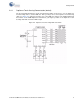
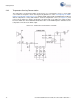
A B C ZVREF ALARM 5 10K 1% R11 R6 1K Ambient Light Detector 560 0603 D VEXP 1 1 TV1 SOT-23 LS1 CSS-J4D20 Q1 2N7002 R8 100 VEXP R19 4.99K 1% LSENSE 25 TV2 TV3 TV4 TV5 Temperature Sensor RT1 10K 1% TSENSE 4 Proximity PRX1 Sensor R7 1 1 Loop RECEPTACLE 1x1 10K .1% R1 D4 2.
Technical Reference Since the FTMF Expansion Card connects the various sensors and output devices to predefined IO of the host CY8C21434, it is important that you follow the pin assignment shown in Figure 3-4 on page 21 and Table 3-1. The schematic for the FTMF Expansion Card shown in Figure 3-4 is found on the CD included in the kit. Table 3-1.
Technical Reference You can use the sensors and output devices in any way you want within your project, but you must make sure to always assign the correct pins within your project. Failure to do so may cause unpredictable or unplanned project results. Referring to Figure 3-4 on page 21, for instance, notice that a capacitor and a resistor connect to Port P0[1] and P3[1]. These two components form the feedback network required for all CapSense.
Technical Reference 24 CY3270 PSoC® FirstTouch™ Guide, Document # 001-15945 Rev.