
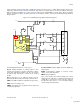
Power Management Low-Cost, Two-Cell Li-Ion/Li-Pol Battery Charger with Cell-Balancing Support Specification Sheet

AN2309
November 25, 2007 Document No. 001-17394 Rev. *B - 10 -
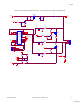
The voltage measurement also is performed by the INA on
the corresponding resistor. The resistive dividers (R7, R6),
(R13, R12), and (R18, R19) transform cell voltage into
signals suitable for the PSoC device. It is very important to
use the high precision resistors in the resistive divider to
obtain a high value common mode signal rejection. The
recommended R6, R7, R12, R13, R18, and R19 tolerances
are 0.1 percent. The following equation depicts the voltage
measurement scheme:
max max
V G V
ADC ina V bat
n n n
VV
ref ref
Equation 18
The value
n
is the ADC code without influence of the INA
and the ADC offset voltage
()n n n
meas offset
. The
value
max
n
is the maximum ADC code and is equal to
2048 for 12-bit incremental ADC in bipolar mode. The value
V
bat
is the battery voltage,
G
ina
is INA gain (1),
V
ref
is
the bandgap reference voltage (1.3V), and
V
is the
resistive divider coefficient (0.25):
1
7
1
6
V
R
R
Equation 19
To provide higher voltage measurement accuracy in
decision-making charging voltages, the following calibration
technique is used. All voltage thresholds are stored as
calibrated ADC codes. During operation, the ADC code of
the battery voltage is compared with these calibrated values.
For this purpose, an external precision 4.2V voltage source
and calibration procedure after assembly are used. All
voltage thresholds are tuned from this precision voltage:
4.2 _
4.2 _
n
V new
nn
new old
n
V old
Equation 20
The value
n
new
is the new voltage threshold ADC code.
The value
n
old
is the old voltage threshold ADC code that
is calculated by using Equation 16 on page 9. The value
4.2 _
n
V new
is the input ADC code during the calibration
procedure. The value
4.2 _
n
V old
is the old voltage
threshold ADC code for 4.2V, which is calculated by using
Equation 16 on page 9. In this way, the calibration is
performed for all decision-making charging voltages
simultaneously. All devices must be calibrated during the
manufacturing process by using external reference.
For temperature measurement, a reference voltage resistive
divider is employed based on a thermistor and a precision
resistor (R6). Thermistor resistance is calculated according
to the voltage drop on the precision resistor and the value of
the reference voltage. To provide the necessary
temperature measurement accuracy, the RefHI reference
voltage is first set, and then AGND. After this, the second
value of the resistor voltage drop is subtracted from the first.
Bias voltages RefHi (2.6V) level in the first step and AGND
(1.3V) in the next step are formed by using the continuous
time user module TestMux. This technique allows
compensation for both the ADC/INA offset error and the
variation in the voltage drop on the current-sense resistor
during the charging/discharging process. The following
equations represent the temperature measurement scheme:
21
R
ref
V V V
t t AGND
RR
ref term
Equation 21
21
R
term
n n n
t t AGND
RR
ref term
Equation 22
The value
1
V
t
is the voltage level on the temperature
reference resistor during application of the
V
AGND
(1.3V)
reference voltage.
2
V
t
is the voltage level on the
temperature reference resistor during application of
V
REFHI
(2.6V) reference voltage.
R
term
is the thermistor
resistance.
R
ref
is the temperature reference resistance
R24 (10K).
1
n
t
and
2
n
t
are the ADC codes of
1
V
t
and
2
V
t
, respectively. The value
n
AGND
is the ADC code of
the AGND input level and is equal to 2048 for 12-bit
incremental ADC in unipolar mode.
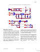
The battery charge/discharge algorithm only needs to check
for temperatures that fall in allowed ranges: during charging
(typical values are 0 to 45 degrees Celsius) and discharging
(typical values are -20 to 60 degrees Celsius). During the
charge phase a hysteresis is added for the lower and upper
bounds in/out temperature. This prevents multiple triggering
when the temperature is close to the preset range. If the
temperature is outside the discharge range, the LOAD
connector is turned off and the PSoC device goes into sleep
mode. Therefore, a hysteresis for the discharge range is not
needed. The temperature profile is shown in Figure 7 on
page 11.
[+] Feedback