
Power Management Low-Cost, Two-Cell Li-Ion/Li-Pol Battery Charger with Cell-Balancing Support Specification Sheet


AN2309
November 25, 2007 Document No. 001-17394 Rev. *B - 14 -
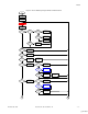
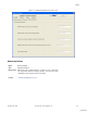
Figure 10. Two-Cell Battery Charger Firmware Flowchart Part 2
State
Charge
Complete
Charge Off
Timers Off
Yes
No
State
Error
Yes
Charge Off
Timers Off
Check Charge
Restart
Condition
Set Initialization
State
Yes
No
State
Wait For
Temperature
Charge Off
Timers Off
Yes
No
True
Yes
No
State
Discharge
Charge Off
Open LOAD Out
Yes
No
Check For
Negative Ich
Set Initialization
State
Yes
No
Check Cell
Balancing
Interval
Cell Balancing
Yes
No
State
Full Discharge
Charge Off
Timers Off
Close LOAD out
Yes
No
Check For
Negative Ich
Set Initialization
State
Yes
No
1 2
Cell Balancing
Reset
Cell Balancing
Reset
Cell Balancing
Reset
Check For
Discharge Stop
Temperature
Set Wait For
Temperature State
Yes
No
Check For
Negative Ich
Yes
No
Set Initialization
State
Check For
Charge Restart
Temperature
Set Initialization
State
Yes
No
Set Wait For
Temperature State
Cell-Balancing Algorithm
At first sight, the cell-balancing algorithm for a two-cell
battery charger appears very simple. The criterion for the
cell imbalance is the voltage difference between the cells.
The cell with a greater voltage must be shunted. But this
algorithm can lead to still more imbalance. During cell
balancing only intrinsic cell voltage must be taken into
account. The voltage portion contributed by the impedance
of the cell leads to errors in cell balancing. In the deep
discharge battery, where the internal resistance of the
battery can be as high as several ohms, the I x R drop
dominates the overall cell voltage. For this reason, cell
balancing is not recommended when the battery pack is
close to deep discharge. Cell balancing during this time can
lead to greater imbalance than before cell balancing was
conducted.
During the 1-C rate charge, the battery has reached
approximately 50 percent of the charged state when its
voltage has risen above 3.9 volts.
If the charging current is less than 1C, this threshold can be
reduced. At this charge state, the internal resistance drops
below 0.2Ω and the distortion level is within acceptable
limits. Therefore, some cell-balancing methods can be
executed if the cell voltage is above the predefined VMID
value (voltage of middle charged state) and the minimum
cell-balance parameter consists of the voltage measure
error value plus the internal impedance error value.
A better practice, which yields more accurate cell voltage
measurements, is to perform the cell sampling operation
after suspending or interrupting the charge current - the
pulse charge technique. With this technique, the charge
operation is temporarily interrupted to permit voltage
measurement of the cells in the pack. Such suspension of
charging eliminates the contribution of cell impedance to cell
voltage measurements and yields more accurate indication
of cell mismatches.
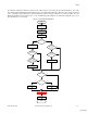
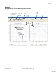
When the pulse charge technique is used, the minimum cell-
balance parameter equals the voltage measure error value
and, therefore, cell balancing can be executed at any time
during the full charge cycle. In the present implementation,
the pulse charge technique is used. As shown in Figure 11
on page 15, the charge operation is interrupted before
voltage measurement.
At the end of the charge process, the shunted current
switching on the cells (to achieve cell balance) can result in
a premature system shutdown. Therefore, during constant
voltage mode of the rapid-charge stage, if the charge
current stays below the minimum cell-balance parameter,
the balancing process stops. Note in Figure 11 the “Check
Out of the Minimum Cell Balancing Current” condition.
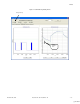
Cell balancing during the discharge phase also is executed
if the maximum cell voltage is above the predefined VMID
value. See in Figure 11 the “Check Out of the VMID
Voltage” condition. The discharge VMID value can differ
from the charge VMID value (described earlier in this
section), and its value is dependent on the discharge rate.
[+] Feedback