
Power Management Low-Cost, Two-Cell Li-Ion/Li-Pol Battery Charger with Cell-Balancing Support Specification Sheet

AN2309
November 25, 2007 Document No. 001-17394 Rev. *B - 6 -
Device Schematic
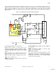
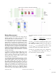
The schematics shown in Figure 4 on page 7 and Figure 5
on page 8 constitute a complete two-cell battery charger.
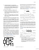
A signal from the PWM goes to the RC-filter, which consists
of resistor R4 and capacitor C4. A constant voltage signal
proportional to the PWM duty cycle value forms at the Q2
gate. Therefore, the PWM and RC-filter is a simple
implementation of a PWM-DAC. The bipolar transistor Q2 is
driven by an analog signal from the PWM-DAC. This bipolar
transistor and resistors R1 and R5 form a resistive divider.
Therefore, the voltage drop on the resistor R1 is directly
dependent on the Q2 base voltage; that is, on the PWM-
DAC level. The MOSFET transistor Q1 is driven by the
voltage drop on resistor R1 and regulates the battery charge
current. The PWM period was set to 2048 for an accurate
current level setting, and can easily be adjusted in the
firmware.
Note that the charger proposed in this application note is
based on a linear current regulator. The advantages of this
regulator are low cost and small size. However, to charge a
battery with a capacity of over 1000 mAh with a charge
current of 1 CA (where CA is the nominal battery capacity)
the linear regulator can be nonoptimal due to the large
voltage drop on the MOSFET and the consequent high
MOSFET temperature. In this case, a step down regulator is
preferable to a linear current regulator. The step-down
regulator is explained in detail in Application Notes AN2107
and AN2258.
Diode D1 is used to prevent a reverse current that can
discharge the battery when the charger is disconnected from
the supply voltage. The cell-balancing circuit is represented
by MOSFETs Q4 and Q5, and by balancing resistors R11
and R14. The MOSFETs are directly controlled from the
PSoC device port (high level - close, low level - open). The
resistors R8-R10 and the bipolar transistor Q3 act as a level
translator and allow opening the MOSFET Q4 by a logic
signal from the PSoC.
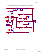
The resistive network (R6, R7, R12, R13, R15, R16, and
R18-R22) and the reference voltage V
bias
from the divider on
R29 and D8, allow transformation of the battery current,
voltage, and temperature into signals suitable for the PSoC
device. The 100 mΩ resistor R23 is a current-sense resistor
that is in the battery pack current path.
The two-cell charger user interface uses two LEDs to
display internal status. In this application configuration, the
green LED indicates the charge phase, and the yellow LED
indicates the discharge phase. The Error state is indicated
when both LEDs are on and the idle status is indicated when
both LEDs are off.
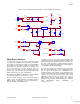
To provide a processor power supply from a high voltage
level, the linear current regulator U2 is used. Alternatively, a
switching regulator can be used, as explained in AN2258.
Or, the regulated step-down converter from an internal SMP
can be used, as explained in AN2180, “Using the PSoC
Switch Mode Pump in a Step-Down Converter.” An external
voltage supply is applied to the connector J4. The SW1
switch allows the device to be disconnected from the
external power supply. Two diodes in the D6 package allow
the processor to operate during the charge phase from the
external power supply and during the discharge phase from
the battery pack power supply. The external load is
connected to the connector J3 LOAD. The diodes D4 and
D5 provide an uninterrupted power supply (UPS) to the
LOAD connector, much as D6 provides power to the
processor. The switch-on transistors Q6 and Q7 allow the
power supply to be disconnected from the LOAD connector
and protect the battery from overdischarge. This switch is
optional and can be removed to reduce total device cost
further. The ground level is connected to the external ground
level POWER (during the charge phase or discharge phase)
and to the battery pack ground that follows the current-
sense resistor. Only in this way can the charge battery pack
current and the total battery pack discharge current pass
through the current-sense resistor. This ground-level
position is used to supplement the battery fuel gauging
functionality in the PSoC software, as shown in AN2294.
[+] Feedback