
Power Management Low-Cost, Two-Cell Li-Ion/Li-Pol Battery Charger with Cell-Balancing Support Specification Sheet

AN2309
November 25, 2007 Document No. 001-17394 Rev. *B - 9 -
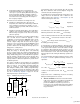
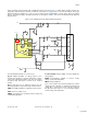
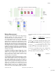
Figure 6. PSoC Internal User Module Configuration
Battery Measurement
To provide a correct implementation of the charge and cell-
balancing algorithms, the charge current, battery voltage
and temperature must be measured accurately.
These three parameters are measured as the voltage drops
on corresponding resistors by using the instrumental
amplifier INA. The measurement is implemented as a two-
stage procedure to eliminate any voltage offset from the INA
and ADC inputs. The INA inputs are shorted together in the
first stage. This state is used to measure INA and ADC
offset voltage. Then the real signal is measured. At this point
the difference between the ADC codes corresponding to the
first and second stages is directly proportional to the battery
measurement parameter without the influence of the INA
and ADC offset voltage.
To transform the battery current (voltage drop on the
current-sense resistor) and battery voltage into levels
suitable for PSoC signals, precise resistive dividers are
used. To limit the current flow from the battery to the
powered-down battery charger, divider resistors of large
nominal resistance are employed.
To provide higher current measurement accuracy, a current-
sense resistor was put in the pack current path close to the
negative battery voltage. In this case, the voltage drop on
the resistive divider (R15, R16, R20, and R21) is
independent of the battery pack voltage level. This is not
true if a current-sense resistor is placed close to the positive
voltage. At the beginning of the charging process, the
voltage bias on the current-sense resistor is measured and
during subsequent processes it is subtracted from the
measured values. In this way, the difference between
resistor values in the resistive divider is partly compensated.
The following equation represents the current measurement
scheme:
max max
V G I R
ADC ina I bat sense
n n n
VV
ref ref
Equation 16
The value
n
is the ADC code without the influence of the
INA and ADC offset voltage and without the voltage bias on
the current-sense resistor (
n n n n
meas offset bias
).
The value
max
n
is the maximum ADC code, which is equal
to 2048 for the 12-bit incremental ADC in bipolar mode.
The value
I
bat
is the battery current,
G
ina
is INA gain (4),
V
ref
is the bandgap reference voltage (1.3V), and
I
is
the resistive divider coefficient (0,833333):
1
20
1
15
I
R
R
Equation 17
[+] Feedback