
Transceiver with Reclocker Specification Sheet

CYV15G0404DXB
Document #: 38-02097 Rev. *B Page 10 of 44
LDTDEN LVTTL Input,
internal pull up
Level Detect Transition Density Enable. When LDTDEN is HIGH, the signal level
detector, range controller, and transition density detector are all enabled to determine
if the RXPLL tracks REFCLKx± or the selected input serial data stream. If the signal
level detector, range controller, or transition density detector are out of their
respective limits while LDTDEN is HIGH, the RXPLL locks to REFCLK± until such a
time they become valid. The (SDASEL[A..D][1:0]) configure the trip level of the signal
level detector. The transition density detector limit is one transition in every 60
consecutive bits. When LDTDEN is LOW, only the range controller determines if the
RXPLL tracks REFCLKx± or the selected input serial data stream. For the cases
when RXCKSELx = 0 (recovered clock), it is recommended to set LDTDEN = HIGH.
RCLKENA
RCLKENB
RCLKENC
RCLKEND
LVTTL Input,
internal pull down
Reclocker Enable. When RCLKENx is HIGH, the RXPLL performs clock and data
recovery functions on the input serial data stream and routes the deserialized data
to the RXDx[7:0] and RXSTA[2:0] parallel data outputs as configured by DECBYPx.
It also presents the reclocked serial data to the enabled differential serial outputs.
When RCLKENx is LOW, the receive reclocker is disabled and the TXDx[7:0] parallel
data inputs and TXCTx[1:0] inputs are interpreted (as configured by ENCBYPx) to
generate appropriate 10-bit characters that are presented to the differential serial
outputs.
The reclocker feature is optimized to be used for SMPTE video applications.
ULCA
ULCB
ULCC
ULCD
LVTTL Input,
internal pull up
Use Local Clock. When ULCx is LOW, the RXPLL is forced to lock to REFCLKx±
instead of the received serial data stream. While ULCx
is LOW, the LFIx for the
associated channel is LOW indicating a link fault.
When ULCx
is HIGH, the RXPLL performs Clock and Data Recovery functions on
the input data streams. This function is used in applications in which a stable
RXCLKx± is needed. In cases when there is an absence of valid data transitions for
a long period of time, or the high-gain differential serial inputs (INx±) are left floating,
there may be brief frequency excursions of the RXCLKx± outputs from REFCLKx±.
SPDSELA
SPDSELB
SPDSELC
SPDSELD
3-Level Select
[4]
static control input
Serial Rate Select. The SPDSELx inputs specify the operating signaling rate range
of each channel’s transmit and receive PLL.
LOW = 195 – 400 MBd
MID = 400 – 800 MBd
HIGH = 800 – 1500 MBd.
INSELA
INSELB
INSELC
INSELD
LVTTL Input,
asynchronous
Receive Input Selector. The INSELx input determines which external serial bit
stream is passed to the receiver’s clock and data recovery circuit. When INSELx is
HIGH, the primary differential serial data input, INx1±, is selected for the associated
receive channel. When INSELx is LOW, the secondary differential serial data input,
INx2±, is selected for the associated receive channel.
LPENA
LPENB
LPENC
LPEND
LVTTL Input,
asynchronous,
internal pull down
Loop Back Enable. The LPENx input enables the internal serial loop back for the
associated channel. When LPENx is HIGH, the transmit serial data from the
associated channel is internally routed to the associated receive Clock and Data
Recovery (CDR) circuit. All enabled serial drivers on the channel are forced to differ-
ential logic-1, and the serial data inputs are ignored. When LPENx is LOW, the
internal serial loop back function is disabled.
Notes
4. 3-Level Select inputs are used for static configuration. These are ternary inputs that make use of logic levels of LOW, MID, and HIGH. The LOW level is usually
implemented by direct connection to V
SS
(ground). The HIGH level is usually implemented by direct connection to V
CC
(power). The MID level is usually
implemented by not connecting the input (left floating), which allows it to self bias to the proper level.
5. See Device Configuration and Control Interface for detailed information on the operation of the Configuration Interface.
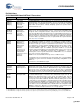
Pin Definitions (continued)
CYV15G0404DXB Quad HOTLink II Transceiver
Name I/O Characteristics Signal Description
[+] Feedback [+] Feedback