
Transceiver with Reclocker Specification Sheet


CYV15G0404DXB
Document #: 38-02097 Rev. *B Page 11 of 44
LFIA
LFIB
LFIC
LFID
LVTTL Output,
asynchronous
Link Fault Indication Output. LFIx is an output status indicator signal. LFIx is the
logical OR of five internal conditions. LFIx
is asserted LOW when any of these condi-
tions are true:
■ Received serial data rate outside expected range
■ Analog amplitude below expected levels
■ Transition density lower than expected
■ Receive channel disabled
■ ULCx is LOW
■ No REFCLKx±.
Device Configuration and Control Bus Signals
WREN
LVTTL input,
asynchronous,
internal pull up
Control Write Enable. The WREN input writes the values of the DATA[7:0] bus into
the latch specified by the address location on the ADDR[3:0] bus.
[5]
ADDR[3:0] LVTTL input
asynchronous,
internal pull up
Control Addressing Bus. The ADDR[3:0] bus is the input address bus used to
configure the device. The WREN input writes the values of the DATA[7:0] bus into the
latch specified by the address location on the ADDR[3:0] bus.
[5]
Tabl e 9 lists the
configuration latches within the device, and the initialization value of the latches upon
the assertion of RESET
. Table 10 shows how the latches are mapped in the device.
DATA[7:0] LVTTL input
asynchronous,
internal pull up
Control Data Bus. The DATA[7:0] bus is the input data bus used to configure the
device. The WREN
input writes the values of the DATA[7:0] bus into the latch
specified by address location on the ADDR[3:0] bus.
[5]
Table 9 lists the configuration
latches within the device, and the initialization value of the latches upon the assertion
of RESET. Tab le 1 0 shows how the latches are mapped in the device.
Internal Device Configuration Latches
RFMODE[A..D][1:0] Internal Latch
[6]
Reframe Mode Select.
FRAMCHAR[A..D] Internal Latch
[6]
Framing Character Select.
DECMODE[A..D] Internal Latch
[6]
Receiver Decoder Mode Select.
DECBYP[A..D] Internal Latch
[6]
Receiver Decoder Bypass.
RXCKSEL[A..D] Internal Latch
[6]
Receive Clock Select.
RXRATE[A..D] Internal Latch
[6]
Receive Clock Rate Select.
SDASEL[A..D][1:0] Internal Latch
[6]
Signal Detect Amplitude Select.
ENCBYP[A..D] Internal Latch
[6]
Transmit Encoder Bypass.
TXCKSEL[A..D] Internal Latch
[6]
Transmit Clock Select.
TXRATE[A..D] Internal Latch
[6]
Transmit PLL Clock Rate Select.
RFEN[A..D] Internal Latch
[6]
Reframe Enable.
RXPLLPD[A..D] Internal Latch
[6]
Receive Channel Power Control.
RXBIST[A..D] Internal Latch
[6]
Receive Bist Disabled.
TXBIST[A..D] Internal Latch
[6]
Transmit Bist Disabled.
OE2[A..D] Internal Latch
[6]
Differential Serial Output Driver 2 Enable.
OE1[A..D] Internal Latch
[6]
Differential Serial Output Driver 1 Enable.
PABRST[A..D] Internal Latch
[6]
Transmit Clock Phase Alignment Buffer Reset.
GLEN[11..0] Internal Latch
[6]
Global Latch Enable.
FGLEN[2..0] Internal Latch
[6]
Force Global Latch Enable.
Note
6. See Device Configuration and Control Interface for detailed information on the internal latches.
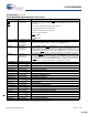
Pin Definitions (continued)
CYV15G0404DXB Quad HOTLink II Transceiver
Name I/O Characteristics Signal Description
[+] Feedback [+] Feedback