
Transceiver with Reclocker Specification Sheet


CYV15G0404DXB
Document #: 38-02097 Rev. *B Page 36 of 44
X3.230 Codes and Notation Conventions
Information transmitted over a serial link is encoded eight bits at
a time into a 10-bit Transmission Character and then sent
serially, bit-by-bit. Information received over a serial link is
collected ten bits at a time, and those transmission characters
that are used for data characters are decoded into the correct
8-bit codes. The 10-bit transmission code supports all 256 8-bit
combinations. Some of the remaining transmission characters
(special characters) are used for functions other than data trans-
mission.
The primary use of a transmission code is to improve the trans-
mission characteristics of a serial link. The encoding defined by
the transmission code ensures that sufficient transitions are
present in the serial bit stream to make clock recovery possible
at the receiver. Such encoding also greatly increases the
likelihood of detecting any single or multiple bit errors that may
occur during transmission and reception of information. In
addition, some special characters of the transmission code
selected by Fibre Channel Standard contain a distinct and easily
recognizable bit pattern that assists the receiver in achieving
character alignment on the incoming bit stream.
Notation Conventions
The documentation for the 8B/10B Transmission Code uses
letter notation for the bits in an 8-bit byte. Fibre Channel Standard
notation uses a bit notation of A, B, C, D, E, F, G, H for the 8-bit
byte for the raw 8-bit data, and the letters a, b, c, d, e, i, f, g, h, j
for encoded 10-bit data. There is a correspondence between bit
A and bit a, B and b, C and c, D and d, E and e, F and f, G and
g, and H and h. Bits i and j are derived, respectively, from
(A,B,C,D,E) and (F,G,H).
The bit labeled A in the description of the 8B/10B Transmission
Code corresponds to bit 0 in the numbering scheme of the FC-2
specification, B corresponds to bit 1, as shown below.
FC-2 bit designation—76543210
HOTLink D/Q designation—76543210
8B/10B bit designation—HGFEDCBA
To clarify this correspondence, the following example shows the
conversion from an FC-2 Valid Data Byte to a Transmission
Character.
FC-2 45H
Bits: 7654
3210
0100 0101
Converted to 8B/10B notation, note that the order of bits has
been reversed):
Data Byte Name D5.2
Bits: ABCDE
FGH
10100 010
Translated to a transmission Character in the 8B/10B Trans-
mission Code:
Bits: abcdei fghj
101001 0101
Each valid transmission character of the 8B/10B Transmission
Code has been given a name using the following convention:
cxx.y, where c is used to show whether the Transmission
Character is a Data Character (c is set to D, and SC/D = LOW)
or a special character (c is set to K, and SC/D = HIGH). When c
is set to D, xx is the decimal value of the binary number
composed of the bits E, D, C, B, and A in that order, and the y is
the decimal value of the binary number composed of the bits H,
G, and F in that order. When c is set to K, xx and y are derived
by comparing the encoded bit patterns of the Special Character
to those patterns derived from encoded valid data bytes and
selecting the names of the patterns most similar to the encoded
bit patterns of the special character.
Using these conventions, the transmission character used for
the examples above, is referred to by the name D5.2. The special
character K29.7 is so named because the first six bits (abcdei)
of this character make up a bit pattern similar to that resulting
from the encoding of the unencoded 11101 pattern (29), and
because the second four bits (fghj) make up a bit pattern similar
to that resulting from the encoding of the unencoded 111 pattern
(7).
Note. This definition of the 10-bit transmission code is based on
the following references, which describe the same 10-bit trans-
mission code.
■ A.X. Widmer and P.A. Franaszek. “A DC-Balanced, Parti-
tioned-Block, 8B/10B Transmission Code” IBM Journal of
Research and Development, 27, No. 5: 440-451 (September, 1983).
■ U.S. Patent 4,486,739. Peter A. Franaszek and Albert X.
Widmer. “Byte-Oriented DC Balanced (0.4) 8B/10B Partitioned
Block Transmission Code” (December 4, 1984).
■ Fibre Channel Physical and Signaling Interface (ANS
X3.230-1994 ANSI FC-PH Standard).
■ IBM Enterprise Systems Architecture/390 ESCON I/O
Interface (document number SA22-7202).
8B/10B Transmission Code
The following information describes how the tables are used for
both generating valid transmission characters (encoding) and
checking the validity of received transmission characters
(decoding). It also specifies the ordering rules followed when
transmitting the bits within a character and the characters within
any higher level constructs specified by a standard.
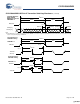
Transmission Order
Within the definition of the 8B/10B transmission code, the bit
positions of the transmission characters are labeled a, b, c, d, e,
i, f, g, h, j. Bit “a” is transmitted first followed by bits b, c, d, e, i,
f, g, h, and j in that order.
Note that bit i is transmitted between bit e and bit f, rather than
in alphabetical order.
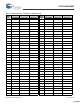
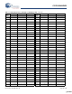
Valid and Invalid Transmission Characters
The following tables define the valid data characters and valid
special characters (K characters), respectively. The tables are
used for both generating valid transmission characters and
checking the validity of received transmission characters. In the
tables, each valid-data-byte or special-character-code entry has
two columns that represent two transmission characters. The
two columns correspond to the current value of the running
disparity. Running disparity is a binary parameter with either a
negative (–) or positive (+) value.
After powering on, the transmitter may assume either a positive
or negative value for its initial running disparity. Upon trans-
[+] Feedback [+] Feedback