
Low Voltage Microcontroller Specification Sheet


CY7C601xx, CY7C602xx
Document 38-16016 Rev. *E Page 20 of 68
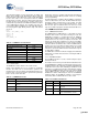
Figure 11-3. SROM Table
11.6.1 Checksum Function
The Checksum function calculates a 16-bit checksum over a
user specifiable number of blocks, within a single Flash macro
(Bank) starting from block zero. The BLOCKID parameter is
used to pass in the number of blocks to calculate the checksum
over. A BLOCKID value of ‘1’ calculates the checksum of only
block 0, while a BLOCKID value of ‘0’ calculates the checksum
of all 256 user blocks. The 16-bit checksum is returned in KEY1
and KEY2. The parameter KEY1 holds the lower eight bits of the
checksum and the parameter KEY2 holds the upper eight bits of
the checksum.
The checksum algorithm executes the following sequence of
three instructions over the number of blocks times 64 to be
checksummed.
romx
add [KEY1], A
adc [KEY2], 0
Va
l
id
Op
e
ra
ti
ng
R
eg
i
o
n
F8h F9h FAh FBh FCh FDh FEh FFh
Table 0
Table 1
Table 2
Table 3
Table 4
Table 5
Table 6
Table 7
Silicon ID
[15-8]
Silicon ID
[7-0]
24 MHz
IOSCTR
at 3.30V
24 MHz
IOSCTR
at 3.00V
24 MHz
IOSCTR
at 2.85V
24 MHz
IOSCTR
at 2.70V
32 KHz
LPOSCTR
at 3.30V
32 KHz
LPOSCTR
at 3.00V
32 KHz
LPOSCTR
at 2.85V
32 KHz
LPOSCTR
at 2.70V
Family /
Die ID
Revision
ID
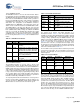
Table 11-12. Checksum Parameters
Name Address Description
KEY1 0,F8h 3Ah
KEY2 0,F9h Stack Pointer value when SSC is
executed
BLOCKID 0,FAh Number of Flash blocks to calculate
checksum on
[+] Feedback [+] Feedback