
Low Voltage Microcontroller Specification Sheet

CY7C601xx, CY7C602xx
Document 38-16016 Rev. *E Page 12 of 68
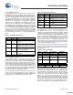
9.2.9 Source Indirect Post Increment
The result of an instruction using this addressing mode is placed
in the Accumulator. Operand 1 is an address pointing to a
location within the memory space, which contains an address
(the indirect address) for the source of the instruction. The
indirect address is incremented as part of the instruction
execution. This addressing mode is only valid on the MVI
instruction. The instruction using this addressing mode is two
bytes in length. Refer to the PSoC Designer: Assembly
Language User Guide for further details on MVI instruction.
Example
9.2.10 Destination Indirect Post Increment
The result of an instruction using this addressing mode is placed
within the memory space. Operand 1 is an address pointing to a
location within the memory space, which contains an address
(the indirect address) for the destination of the instruction. The
indirect address is incremented as part of the instruction
execution. The source for the instruction is the Accumulator. This
addressing mode is only valid on the MVI instruction. The
instruction using this addressing mode is two bytes in length.
Example
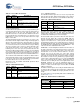
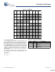
10. Instruction Set Summary
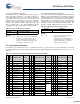
The instruction set is summarized in Table 10-1 numerically and serves as a quick reference. For more information, the Instruction
Set Summary tables are described in detail in the PSoC Designer Assembly Language User Guide (available on the www.cypress.com
web site).
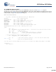
Table 9-15. Source Indirect Post Increment
Opcode Operand 1
Instruction Source Address Address
MVI A, [8] ;In this case, the value in the memory location
at address 8 is an indirect address. The
memory location pointed to by the Indirect
address is moved into the Accumulator. The
indirect address is then incremented.
Table 9-16. Destination Indirect Post Increment
Opcode Operand 1
Instruction Destination Address Address
MVI [8], A ;In this case, the value in the memory
location at address 8 is an
indirect;address. The Accumulator is
moved into the memory location pointed
to by the indirect address. The indirect
address is then incremented.
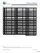
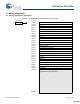
Table 10-1. Instruction Set Summary Sorted Numerically by Opcode Order
Opcode Hex
Cycles
Bytes
Instruction Format
[1, 2]
Flags
Opcode Hex
Cycles
Bytes
Instruction Format Flags
Opcode Hex
Cycles
Bytes
Instruction Format Flags
00 15 1 SSC 2D 8 2 OR [X+expr], A Z 5A 5 2 MOV [expr], X
01 4 2 ADD A, expr C, Z 2E 9 3 OR [expr], expr Z 5B 4 1 MOV A, X Z
02 6 2 ADD A, [expr] C, Z 2F 10 3 OR [X+expr], expr Z 5C 4 1 MOV X, A
03 7 2 ADD A, [X+expr] C, Z 30 9 1 HALT 5D 6 2 MOV A, reg[expr] Z
04 7 2 ADD [expr], A C, Z 31 4 2 XOR A, expr Z 5E 7 2 MOV A, reg[X+expr] Z
05 8 2 ADD [X+expr], A C, Z 32 6 2 XOR A, [expr] Z 5F 10 3 MOV [expr], [expr]
06 9 3 ADD [expr], expr C, Z 33 7 2 XOR A, [X+expr] Z 60 5 2 MOV reg[expr], A
07 10 3 ADD [X+expr], expr C, Z 34 7 2 XOR [expr], A Z 61 6 2 MOV reg[X+expr], A
08 4 1 PUSH A 35 8 2 XOR [X+expr], A Z 62 8 3 MOV reg[expr], expr
09 4 2 ADC A, expr C, Z 36 9 3 XOR [expr], expr Z 63 9 3 MOV reg[X+expr],
expr
0A 6 2 ADC A, [expr] C, Z 37 10 3 XOR [X+expr], expr Z 64 4 1 ASL A C, Z
0B 7 2 ADC A, [X+expr] C, Z 38 5 2 ADD SP, expr 65 7 2 ASL [expr] C, Z
0C 7 2 ADC [expr], A C, Z 39 5 2 CMP A, expr if (A=B)
Z=1
if (A<B)
C=1
66 8 2 ASL [X+expr] C, Z
0D 8 2 ADC [X+expr], A C, Z 3A 7 2 CMP A, [expr] 67 4 1 ASR A C, Z
0E 9 3 ADC [expr], expr C, Z 3B 8 2 CMP A, [X+expr] 68 7 2 ASR [expr] C, Z
0F 10 3 ADC [X+expr], expr C, Z 3C 8 3 CMP [expr], expr 69 8 2 ASR [X+expr] C, Z
10 4 1 PUSH X 3D 9 3 CMP [X+expr], expr 6A 4 1 RLC A C, Z
11 4 2 SUB A, expr C, Z 3E 10 2 MVI A, [ [expr]++ ] Z 6B 7 2 RLC [expr] C, Z
12 6 2 SUB A, [expr] C, Z 3F 10 2 MVI [ [expr]++ ], A 6C 8 2 RLC [X+expr] C, Z
[+] Feedback [+] Feedback