
Low Voltage Microcontroller Specification Sheet

CY7C601xx, CY7C602xx
Document 38-16016 Rev. *E Page 48 of 68
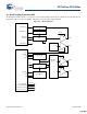
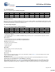
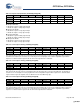
18.1.2 Time Capture
enCoRe II LV has two 8-bit captures. Each capture has a separate register for rising and falling time. The two 8-bit captures can be
configured as a single 16-bit capture. When configured in this way, the capture 1 registers hold the high order byte of the 16-bit timer
capture value. Each of the four capture registers can be programmed to generate an interrupt when it is loaded.
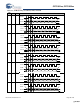
Figure 18-2. Time Capture Block Diagram
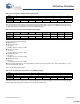
Table 18-2. Free Running Timer High Order Byte (FRTMRH) [0x21] [R/W]
Bit # 7 6 5 4 3 2 1 0
Field Free Running Timer [15:8]
Read/Write R/W R/W R/W R/W R/W R/W R/W R/W
Default 0 0 0 0 000 0
Bit [7:0]: Free Running Timer [15:8]
When reading the free running timer, the low order byte is read first and the high order second. When writing, the low order byte
is written first, then the high order byte.
Table 18-3. Timer Configuration (TMRCR) [0x2A] [R/W]
Bit # 7 6 5 4 3 2 1 0
Field First Edge Hold 8-bit Capture Prescale [2:0] Cap0 16-bit
Enable
Reserved
Read/Write R/W R/W R/W R/W R/W – – –
Default 0 0 0 0 000 0
Bit 7: First Edge Hold
The First Edge Hold function applies to all four capture timers.
0 = The time of the most recent edge is held in the Capture Timer Data Register. If multiple edges have occurred since reading
the capture timer, the time for the most recent one is read.
1 = The time of the first occurrence of an edge is held in the Capture Timer Data Register until the data is read. Subsequent
edges are ignored until the Capture Timer Data Register is read.
Bit [6:4]: 8-bit Capture Prescale [2:0]
This field controls which eight bits of the 16 Free Running Timer are captured when in bit mode.
0 0 0 = capture timer[7:0]
0 0 1 = capture timer[8:1]
0 1 0 = capture timer[9:2]
0 1 1 = capture timer[10:3]
1 0 0 = capture timer[11:4]
1 0 1 = capture timer[12:5]
1 1 0 = capture timer[13:6]
1 1 1 = capture timer[14:7]
Bit 3: Cap0 16-bit Enable
0 = Capture 0 16-bit mode is disabled
1 = Capture 0 16-bit mode is enabled. Capture 1 is disabled and the Capture 1 rising and falling registers are used as an extension
to the Capture 0 registers—extending them to 16 bits.
Bit [2:0]: Reserved
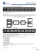
Source Control and
Configuration
External
Clock
Internal
24-MHz
Oscillator
Internal
Low Power
32-KHz
Oscillator
Timer Capture
Clock Output
(4-MHz Default)
Programmable
Interval Timer
16-bit Free
Running Counter
[+] Feedback [+] Feedback