
Low Voltage Microcontroller Specification Sheet

CY7C601xx, CY7C602xx
Document 38-16016 Rev. *E Page 56 of 68
19.4.2 Interrupt Mask Registers
The Interrupt Mask Registers (INT_MSKx) enable the individual
interrupt sources’ ability to create pending interrupts.
There are four Interrupt Mask Registers (INT_MSK0,
INT_MSK1, INT_MSK2, and INT_MSK3) which are referred to in
general as INT_MSKx. If cleared, each bit in an INT_MSKx
register prevents a posted interrupt from becoming a pending
interrupt (input to the priority encoder). However, an interrupt can
still post even if its mask bit is zero. All INT_MSKx bits are
independent of all other INT_MSKx bits.
If an INT_MSKx bit is set, the interrupt source associated with
that mask bit generates an interrupt that becomes a pending
interrupt.
The Enable Software Interrupt (ENSWINT) bit in INT_MSK3[7]
determines the way an individual bit value written to an
INT_CLRx register is interpreted. When cleared, writing 1s to an
INT_CLRx register has no effect. However, writing 0s to an
INT_CLRx register, when ENSWINT is cleared, causes the
corresponding interrupt to clear. If the ENSWINT bit is set, 0s
written to the INT_CLRx registers are ignored. However, 1s
written to an INT_CLRx register, when ENSWINT is set, causes
an interrupt to post for the corresponding interrupt.
Software interrupts aid in debugging interrupt service routines by
eliminating the need to create system level interactions that are
sometimes necessary to create a hardware only interrupt.
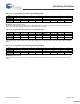
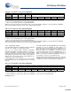
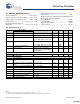
Table 19-3. Interrupt Clear 1 (INT_CLR1) [0xDB] [R/W]
Bit # 7 6 5 4 3 2 1 0
Field TCAP0 Prog Interval
Timer
1-ms Program-
mable Interrupt
Reserved
Read/Write R/W R/W R/W – ––– –
Default 0 0 0 0 000 0
When reading this register,
0 = There is no posted interrupt for the corresponding hardware.
1 = There is a posted interrupt for the corresponding hardware.
Writing a ‘0’ to the bits clears the posted interrupts for the corresponding hardware. Writing a ‘1’ to the bits AND to the ENSWINT
(Bit 7 of the INT_MSK3 Register) posts the corresponding hardware interrupt.
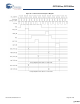
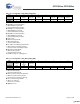
Table 19-4. Interrupt Clear 2 (INT_CLR2) [0xDC] [R/W]
Bit # 7 6 5 4 3 2 1 0
Field Reserved GPIO Port 4 GPIO Port 3 GPIO Port 2 Reserved INT2 16-bit Counter
Wrap
TCAP1
Read/Write – R/W R/W R/W –R/WR/W R/W
Default 0 0 0 0 000 0
When reading this register,
0 = There is no posted interrupt for the corresponding hardware.
1 = There is a posted interrupt for the corresponding hardware.
Writing a ‘0’ to the bits clears the posted interrupts for the corresponding hardware. Writing a ‘1’ to the bits AND to the ENSWINT
(Bit 7 of the INT_MSK3 Register) posts the corresponding hardware interrupt.
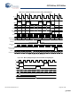
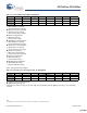
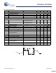
Table 19-5. Interrupt Mask 3 (INT_MSK3) [0xDE] [R/W]
Bit # 7 6 5 4 3 2 1 0
Field ENSWINT Reserved
Read/Write R – – – – – – –
Default 0 0 0 0 000 0
Bit 7: Enable Software Interrupt (ENSWINT)
0= Disable. Writing 0s to an INT_CLRx register, when ENSWINT is cleared, clears the corresponding interrupt.
1= Enable. Writing 1s to an INT_CLRx register, when ENSWINT is set, posts the corresponding interrupt.
Bit [6:0]: Reserved
[+] Feedback [+] Feedback