
Low Speed USB Peripheral Controller Specification Sheet

CY7C63310, CY7C638xx
Document 38-08035 Rev. *K Page 10 of 83
7.2.2 Source Direct
The result of an instruction using this addressing mode is placed
in either the A register or the X register, which is specified as part
of the instruction opcode. Operand 1 is an address that points to
a location in the RAM memory space or the register space that
is the source of the instruction. Arithmetic instructions require
two sources; the second source is the A register or X register
specified in the opcode. Instructions using this addressing mode
are two bytes in length.
Examples
7.2.3 Source Indexed
The result of an instruction using this addressing mode is placed
in either the A register or the X register, which is specified as part
of the instruction opcode. Operand 1 is added to the X register
forming an address that points to a location in the RAM memory
space or the register space that is the source of the instruction.
Arithmetic instructions require two sources; the second source is
the A register or X register specified in the opcode. Instructions
using this addressing mode are two bytes in length.
Examples
7.2.4 Destination Direct
The result of an instruction using this addressing mode is placed
within the RAM memory space or the register space. Operand 1
is an address that points to the location of the result. The source
for the instruction is either the A register or the X register, which
is specified as part of the instruction opcode. Arithmetic instruc-
tions require two sources; the second source is the location
specified by Operand 1. Instructions using this addressing mode
are two bytes in length.
Examples
7.2.5 Destination Indexed
The result of an instruction using this addressing mode is placed
within the RAM memory space or the register space. Operand 1
is added to the X register forming the address that points to the
location of the result. The source for the instruction is the A
register. Arithmetic instructions require two sources; the second
source is the location specified by Operand 1 added with the X
register. Instructions using this addressing mode are two bytes
in length.
Example
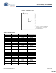
Table 7-8. Source Direct
Opcode Operand 1
Instruction Source Address
ADD A [7] The value in the RAM memory location at
address 7 is added with the Accumulator,
and the result is placed in the Accumu-
lator.
MOV X REG[8] The value in the register space at address
8 is moved to the X register.
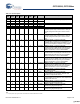
Table 7-9. Source Indexed
Opcode Operand 1
Instruction Source Index
ADD A [X+7] The value in the memory location at
address X + 7 is added with the
Accumulator, and the result is placed
in the Accumulator.
MOV X REG[X+8] The value in the register space at
address X + 8 is moved to the X
register.
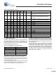
Table 7-10. Destination Direct
Opcode Operand 1
Instruction Destination Address
ADD [7] A The value in the memory location at
address 7 is added with the Accumu-
lator, and the result is placed in the
memory location at address 7. The
Accumulator is unchanged.
MOV REG[8] A The Accumulator is moved to the
register space location at address 8.
The Accumulator is unchanged.
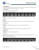
Table 7-11. Destination Indexed
Opcode Operand 1
Instruction Destination Index
ADD [X+7] A The value in the; memory location at
address X+7 is added with the Accumu-
lator, and the result is placed in the
memory location at address x+7. The
Accumulator is unchanged.
[+] Feedback [+] Feedback