
Low Speed USB Peripheral Controller Specification Sheet

CY7C63310, CY7C638xx
Document 38-08035 Rev. *K Page 7 of 83
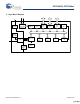
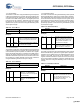
6. CPU Architecture
This family of microcontrollers is based on a high performance,
8-bit, Harvard architecture microprocessor. Five registers control
the primary operation of the CPU core. These registers are
affected by various instructions, but are not directly accessible
through the register space by the user.
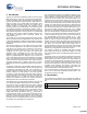
The 16-bit Program Counter Register (CPU_PC) allows direct
addressing of the full 8 Kbytes of program memory space.
The Accumulator Register (CPU_A) is the general purpose
register, which holds the results of instructions that specify any
of the source addressing modes.
The Index Register (CPU_X) holds an offset value that is used
in the indexed addressing modes. Typically, this is used to
address a block of data within the data memory space.
The Stack Pointer Register (CPU_SP) holds the address of the
current top of the stack in the data memory space. It is affected
by the PUSH, POP, LCALL, CALL, RETI, and RET instructions,
which manage the software stack. It is also affected by the SWAP
and ADD instructions.
The Flag Register (CPU_F) has three status bits: Zero Flag bit
[1]; Carry Flag bit [2]; Supervisory State bit [3]. The Global
Interrupt Enable bit [0] globally enables or disables interrupts.
The user cannot manipulate the Supervisory State status bit [3].
The flags are affected by arithmetic, logic, and shift operations.
The manner in which each flag is changed is dependent upon
the instruction being executed, such as AND, OR, XOR, and
others. See Table 8-1 on page 12.
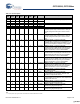
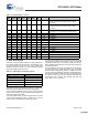
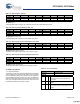
2 4 4 3 8 2 6 P0.5/TIO0 GPIO Port 0 bit 5. Configured individually
Alternate function Timer capture inputs or Timer
output TIO0
1 3 3 2 7 1 5 P0.6/TIO1 GPIO Port 0 bit 6. Configured individually
Alternate function Timer capture inputs or Timer
output TIO1
32 2 2 1 6 P0.7 GPIO Port 0 bit 7. Configured individually
Not present in the 16 pin PDIP or SOIC package
10 1 1 NC No connect
11 12 24 NC No connect
12 NC No connect
17 NC No connect
19 NC No connect
27 NC No connect
28 NC No connect
29 NC No connect
30 NC No connect
31 NC No connect
16 16 15 12 17 11 15 Vcc Supply
13 13 12 9 14 8 12 V
SS
Ground
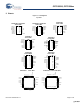
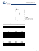
Table 5-2. Pin Description (continued)
32
QFN
24
QSOP
24
SOIC
18
SIOC
18
PDIP
16
SOIC
16
PDIP
Name Description
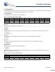
Table 6-1. CPU Registers and Register Names
CPU Register Register Name
Flags CPU_F
Program Counter CPU_PC
Accumulator CPU_A
Stack Pointer CPU_SP
Index CPU_X
[+] Feedback [+] Feedback