
Full Speed USB Controller Specification Sheet


CY7C64215
Document 38-08036 Rev. *C Page 20 of 30
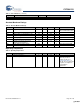
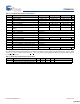
DC Programming Specifications
The following table lists guaranteed maximum and minimum specifications for the voltage and temperature ranges: 4.75V to 5.25V
and 0°C <
T
A
< 70°C, or 3.0V to 3.6V and 0°C < T
A
< 70°C, respectively. Typical parameters apply to 5V and 3.3V at 25°C and are
for design guidance only.
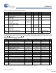
Table 17. DC Programming Specifications
Parameter Description Min Typ Max Unit Notes
I
DDP
Supply Current During Programming or
Verify
– 15 30 mA
V
ILP
Input Low Voltage During Programming or
Verify
– – 0.8 V
V
IHP
Input High Voltage During Programming or
Verify
2.1 – – V
I
ILP
Input Current when Applying Vilp to P1[0]
or P1[1] During Programming or Verify
– – 0.2 mA Driving internal pull-down resistor.
I
IHP
Input Current when Applying Vihp to P1[0]
or P1[1] During Programming or Verify
– – 1.5 mA Driving internal pull-down resistor.
V
OLV
Output Low Voltage During Programming
or Verify
– – Vss + 0.75 V
V
OHV
Output High Voltage During Programming
or Verify
Vdd
– 1.0 – Vdd V
Flash
ENPB
Flash Endurance (per block) 50,000 – – – Erase/write cycles per block.
Flash
ENT
Flash Endurance (total)
[6]
1,800,000 – – – Erase/write cycles.
Flash
DR
Flash Data Retention 10 – – Years
Note
6. A maximum of 36 x 50,000 block endurance cycles is allowed. This may be balanced between operations on 36x1 blocks of 50,000 maximum cycles each,
36x2 blocks of 25,000 maximum cycles each, or 36x4 blocks of 12,500 maximum cycles each (to limit the total number of cycles to 36x50,000 and that no
single block ever sees more than 50,000 cycles).
For the full industrial range, the user must employ a temperature sensor user module (FlashTemp) and feed the result to the temperature argument before
writing. Refer to the Flash APIs Application Note AN2015 at http://www.cypress.com under Application Notes for more information.
[+] Feedback [+] Feedback