
Full Speed USB Controller Specification Sheet


CY7C64215
Document 38-08036 Rev. *C Page 6 of 30
Each user module establishes the basic register settings that
implement the selected function. It also provides parameters that
allow you to tailor its precise configuration to your particular
application. For example, a Pulse Width Modulator User Module
configures one or more digital PSoC blocks, one for each 8 bits
of resolution. The user module parameters permit the designer
to establish the pulse width and duty cycle. User modules also
provide tested software to cut development time. The user
module application programming interface (API) provides
high-level functions to control and respond to hardware events
at run-time. The API also provides optional interrupt service
routines that is adapted as needed.
The API functions are documented in user module data sheets
that are viewed directly in the PSoC Designer IDE. These data
sheets explain the internal operation of the user module and
provide performance specifications. Each data sheet describes
the use of each user module parameter and documents the
setting of each register controlled by the user module.
The development process starts when you open a new project
and bring up the Device Editor/Chip Layout View, a graphical
user interface (GUI) for configuring the hardware. You pick the
user modules you need for your project and map them onto the
PSoC blocks with point-and-click simplicity. Next, you build
signal chains by interconnecting user modules to each other and
the IO pins. At this stage, you also configure the clock source
connections and enter parameter values directly or by selecting
values from drop-down menus. When you are ready to test the
hardware configuration or move on to developing code for the
project, you perform the “Generate Application” step. This
causes PSoC Designer to generate source code that automati-
cally configures the device to your specification and provides the
high-level user module API functions.
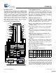
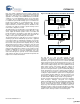
Figure 4. User Module and Source Code Development Flows
The next step is to write your main program, and any
sub-routines using PSoC Designer’s Application Editor
subsystem. The Application Editor includes a Project Manager
that allows you to open the project source code files (including
all generated code files) from a hierarchal view. The source code
editor provides syntax coloring and advanced edit features for
both C and assembly language. File search capabilities include
simple string searches and recursive “grep-style” patterns. A
single mouse click invokes the Build Manager. It employs a
professional-strength “makefile” system to automatically analyze
all file dependencies and run the compiler and assembler as
necessary. Project level options control optimization strategies
used by the compiler and linker. Syntax errors are displayed in a
console window. Double clicking the error message takes you
directly to the offending line of source code. When all is correct,
the linker builds a HEX file image suitable for programming.
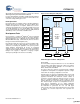
The last step in the development process takes place inside the
PSoC Designer’s Debugger subsystem. The Debugger
downloads the HEX image to the In-Circuit Emulator (ICE CUBE)
where it runs at full speed. Debugger capabilities rival those of
systems costing many times more. In addition to traditional
single-step, run-to-breakpoint and watch-variable features, the
Debugger provides a large trace buffer and allows you define
complex breakpoint events that include monitoring address and
data bus values, memory locations and external signals.
Debugger
Inter face
to ICE
Application Editor
Device Editor
Project
Manager
Source
Code
Editor
Storage
Inspector
User
Module
Selection
Placement
and
Par ameter
-ization
Generate
Application
Build
All
Event &
Breakpoint
Manager
Build
Manager
Source
Code
Generator
[+] Feedback [+] Feedback