
Independent Clock Deserializing Reclocker Specification Sheet

CYV15G0404RB
Document #: 38-02102 Rev. *C Page 9 of 27
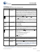
LDTDEN LVTTL Input,
internal pull up
Level Detect Transition Density Enable. When LDTDEN is HIGH, the Signal
Level Detector, Range Controller, and Transition Density Detector are all enabled
to determine if the RXPLL tracks TRGCLKx± or the selected input serial data
stream. If the Signal Level Detector, Range Controller, or Transition Density
Detector are out of their respective limits while LDTDEN is HIGH, the RXPLL locks
to TRGCLKx± until they become valid. The SDASEL[A..D][1:0] inputs configure
the trip level of the Signal Level Detector. The Transition Density Detector limit is
one transition in every 60 consecutive bits. When LDTDEN is LOW, only the
Range Controller determines if the RXPLL tracks TRGCLKx± or the selected input
serial data stream. Set LDTDEN = HIGH.
ULCA
ULCB
ULCC
ULCD
LVTTL Input,
internal pull up
Use Local Clock. When ULCx is LOW, the RXPLL locks to TRGCLKx± instead
of the received serial data stream. While ULCx
is LOW, the LFIx for the associated
channel is LOW, indicating a link fault.
When ULCx
is HIGH, the RXPLL performs Clock and Data Recovery functions on
the input data streams. This function is used in applications that need a stable
RXCLKx±. When valid data transitions are absent for a long time, or the high-gain
differential serial inputs (INx±) are left floating, the RXCLKx± outputs may briefly
be different from TRGCLKx±.
SPDSELA
SPDSELB
SPDSELC
SPDSELD
3-Level Select
[2]
static control input
Serial Rate Select. The SPDSELx inputs specify the operating signaling-rate
range of each channel’s receive PLL.
LOW = 195–400 MBd
MID = 400–800 MBd
HIGH = 800–1500 MBd.
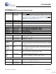
INSELA
INSELB
INSELC
INSELD
LVTTL Input,
asynchronous
Receive Input Selector. The INSELx input determines which external serial bit
stream passes to the receiver’s Clock and Data Recovery circuit. When INSELx
is HIGH, the Primary Differential Serial Data Input, INx1±, is the associated receive
channel. When INSELx is LOW, the Secondary Differential Serial Data Input,
INx2±, is the associated receive channel.
LFIA
LFIB
LFIC
LFID
LVTTL Output,
asynchronous
Link Fault Indication Output. LFIx is an output status indicator signal. LFIx is the
logical OR of six internal conditions. LFIx
asserts LOW when any of the following
conditions is true:
• Received serial data rate is outside expected range
• Analog amplitude is below expected levels
• Transition density is lower than expected
• Receive is channel disabled
•ULCx
is LOW
• TRGCLKx± is absent.
Device Configuration and Control Bus Signals
WREN
LVTTL input,
asynchronous,
internal pull up
Control Write Enable. The WREN input writes the values of the DATA[7:0] bus
into the latch specified by the address location on the ADDR[3:0] bus.
[3]
ADDR[3:0] LVTTL input
asynchronous,
internal pull up
Control Addressing Bus. The ADDR[3:0] bus is the input address bus that
configures the device. The WREN
input writes the values of the DATA[7:0] bus
into the latch specified by the address location on the ADDR[3:0] bus.
[3]
Table 3,
“Device Configuration and Control Latch Descriptions,” on page 14 lists the config-
uration latches within the device, and the initialization value of the latches when
RESET
is asserted. Table 4, “Device Control Latch Configuration Table,” on
page 16 shows how the latches are mapped in the device.
Notes
2. Use 3-Level Select inputs for static configuration. These are ternary inputs that use logic levels of LOW, MID, and HIGH. To implement the LOW level, connect
directly to V
SS
(ground). To implement the HIGH level, connect directly to V
CC
(power). To implement the MID level, do not connect the input (leave floating),
which allows it to self bias to the proper level.
3. See “Device Configuration and Control Interface” on page 13 for detailed information about the operation of the Configuration Interface.
Pin Definitions (continued)
CYV15G0404RB Quad HOTLink II Deserializing Reclocker
Name IO Characteristics Signal Description
[+] Feedback