SPX-5500 Series Operations Manual RF 900Mhz Suprex® Reader SPX-5511 pictured SPX-5500SS
Cypress Suprex SPX-5500 Series Overview: The SPX-5500 series of RF Wireless solutions provide a wireless bridge from card readers with gates or door hardware to most access control manufacturerʼs panels. The SPX or Suprex products include both the remote ( Door/Gate ) unit and the central ( AC Panel ) unit. Features: -- Service mode for setup and configuration.
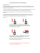
External connections and DIP Switch Settings 1-Relay1 Input 2-Relay2 Input 3-Aux Out 4-Ground 5-RLY3 N.C. 6-RLY3 Com 7-RLY3 N.O. 8-RLY4 N.C. 9-RLY4 Com 10-RLY4 N.O. 1-D0/CLK Output 2-D1/Data Output 3-LED In 4-Prog Res 1 5-Prog Res 2 6-+5 VDC Out 7-N/C 8-N/C RFX SPX-5500 - 5000 Series Central Unit Diagnostic LED 1-Ground 2-8 to 16 VDC In N/C N/C 3-Aux Input 4-Ground 5-RLY1 N.C. 6-RLY1 Com 7-RLY1 N.O. 8-RLY2 N.C. 9-RLY2 Com 10-RLY2 N.O.
Quick Reference For Typical Connections SPX-5000 Series Central Quick Reference R1 IN R1 Input Controls Strike on Remote D0/Clock D1/Data LED D0/Clock Out D1/Data Out LED In Access Control Panel Switch #4 ON Disable Pullup Resistors Switch #4 OFF Enable Pullup Resistors Diagnostic LED (-) Ground +8 to +16 VDC (+) Suprex RF Central Typical Suprex Central Connections DC Power Supply 1 2 3 4 5 6 7 8 Switch 6 7 8 Wiegand Wiegand / No Filter Strobed Rising Edge (MR-5) Strobed Rising Edge (Dorad0 644)
Cypress Suprex RF Series - Introduction SPX-5000 Series: This manual covers the operation and setup of the Cypress Suprex RF (5000 Series) units. Several configurations are available with different enclosure and antenna options. All of the units with the 5000 series part number will have the same operational functions and electrical connections. Features: -- DES56 Encryption for secure communications -- Units are factory configured as matched pairs, no field channel setting is required.
Unpacking: Cypress Suprex RF Series - Setup and Preinstallation Remove covers from units and check interior for any shipping damage. Remove any packing material if present. Inventory any included parts (depending on model) such as antennas, coax cables etc. Bench Testing: Before installing the units in the field they should be assembled and tested at a convenient “Bench top” location. This will make it easier to verify / change settings and check operation when both units are visible at the same time.
Cypress Suprex RF Series - Indicators and Operating Modes LED Diagnostic Indicator: The LED Diagnostic indicator provides information on the operational status of the unit. If the units are not communicating, viewing the diagnostic indicator LEDʼs may help to determine the nature of the problem.
Cypress Suprex RF Series - Field Installation Mounting the Units: A site evaluation should have determined the optimal locations for the Central and Remote units, the type of antennas that would be needed, and the frequency band to be used. (See Cypress Application Note “Site Evaluation for Duprex RF products”). This section of the document covers units that utilize the enclosure mounted1/2 wave whip antenna.
Cypress Suprex RF Series - Field Installation This orientation may reduce range. The metal pole is placed between antenna and other unit and the antenna is close to metal. The units should be mounted in such a way that there is as clear of a path as possible between the 2 units. If mounting to a post or wall the unit should be placed where it has minimal interference with the antenna. Maximum signal and ranges are achieved when the antenna is clear of obstructions and is placed away from metal objects.
Cypress Suprex RF Series - Door Strike and LED I/O Note: The LED and Door Strike operation of the RF Suprex differs from previous Suprex versions. To activate the relay on the Remote unit, connect as shown below. These connections can be used to allow the Remote relay to operate a DOOR STRIKE, GATE, or other locking hardware. Refer to following pages in this document for details of each I/O operation and connection. There are two relays available for accessory outputs at the Remote end.
Cypress Suprex RF Series - Door Strike and LED I/O The Cypress RFX-5000 provides additional data channels to support access control hardware such as door strikes, tamper alarms, request to exit status, etc. These signals are sent to and from the Remote and Central units without the need to run additional wiring. The accessory control I/O use active low inputs. When the inputs are floating (nothing connected) the associated output will be set to a high level.
Cypress Suprex RF Series - Relay Controls Input Signal Relay 1 IN Suprex RF Central Contact Outputs Relay 1 N.C Relay 1 Com Relay 1 N.O.
Cypress Suprex RF Series - Relay Controls Input Signal Relay 2 IN Suprex RF Central Contact Outputs Relay 2 N.C Relay 2 Com Relay 2 N.O.
Cypress Suprex RF Series - Relay Controls Contact Outputs Relay 3 N.C Relay 3 Com Relay 3 N.O. Suprex RF Central Input Signal Relay 3 IN Suprex RF Remote Relay 3 functions as an Alarm relay and monitors the condition of the communication link between the Central and Remote units. Relay 3 is activated when power is applied and the communication link between the Central and Remote is functioning.
Cypress Suprex RF Series - Relay Controls Contact Outputs Relay 4 N.C Relay 4 Com Relay 4 N.O.
Cypress Suprex RF Series - Auxillary I/O Aux Output Signal AUX OUT Suprex RF Central Aux Input Signal AUX IN Suprex RF Remote