! CYPRESS */5&(3"5*0/ 40-65*0/4 WMR-2000 SYSTEM ! ! ! Operations Manual Wireless Mobile Reader ! WMR-2000-V3_MAN_0314
System Overview! ! Cypress’ Wireless Mobile Readers provide a unique portable credential verification solution. The WMR system includes a wiegand or serial panel interface for real-time verification. Common applications include Assembly Attendance, Random Challenge, Mustering and High volume Cardholder Traffic logging Other common credentialing challenges can be easily solved with the WMR series of solutions.
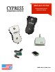
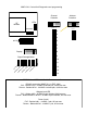
Unpack Units RPT-5651! Optional Repeater WMR-7211 Base Unit WMR-7XXX Mobile Unit WMR-BATT-NiMH Belt Holster! WMR-HOLB WMR-PRCX! Programming cards! (if required) Smartcharger for NiMH Batteries (not included) Wiegand Expansion ! EXP-1000C Remove cover from Central unit and check interior for any shipping damage. ! Remove any packing material if present.! ! Before installing the units in the field they should be assembled and tested at a convenient “Bench top” location.
! System Description The Wireless Mobile Reader is the newest member of the Suprex family of products.! ! The WMR products are based on the Suprex SPX-5600 series of products and they support a wide range of additional features:! ! Additional features:! ! -- AES Encryption for secure communications upon request! -- No channel selection is required as the units are preconfigured at the factory.
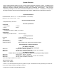
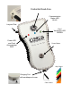
Credential Read Area Communication ! Status LED! BLUE Lanyard Post Card! Verification LED! GREEN Power LED! and Card Acknowledge! RED Power Button Grip Colors Charging Port ! with weatherproof cover Case Colors
! Operation:! ! The Handheld Remote reader unit will read a Wiegand RF proximity badges. The badge data is sent! through a radio link to a Central panel interface module that generates Wiegand data for a connected access control panel.! ! An access control panel determines whether the badge is valid or invalid. When valid badge data is presented, the panel will trigger either an LED, Strike Relay output, or both, depending upon the type of panel.
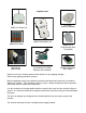
External connections and DIP Switch Settings ! 1 - 8 to 16 VDC In ! 2 - Ground ! 1- Relay 4 N.O.! 2- Relay 4 Com! 3 - Relay 4 N.C.! 4 - Relay 3 N.O.! 5 - Relay 3 Com! 6 - Relay 3 N.C.
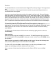
! Cypress WMR-2000 - Wiegand Expansion Module! Panel “Central” interface DC! Power ! Supply +8 to +16 VDC! Ground EXP(+)! EXP(-)! WMR-7211! Central ! ! ! Access! Control ! Panel LED In D1/Data Out! D0/Clock Out 8 to 16 VDC In! Ground 485(+)! 485(-)! +5 VDC Out! Prog Res 2! Prog Res 1! LED Input! D1/Data/F2F Out ! D0/Clock Out * EXP-1000! Central Unit R1 IN RLY4 N.O.! RLY4 Com! RLY4 N.C.! RLY3 N.O.! RLY3 Com! RLY3 N.C.
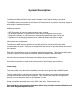
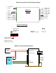
WMR-7211 Central Unit Diagnostics and programming ! Channel! Selection Address ! Selection LEDs RF Module 1234 DIP Switch 567 2 3 4 All Off 5 1 2 3 4 5 6 7 8 9 10 6 7 Display 8 9 Signal Strength Meter 10 bm to 0d db m to 12 -2 0 db 13 -4 0d bm bm m bm -2 0 -4 0d to -6 0d bm 0d bm m db to -6 0d -8 -9 0d bm to N o -8 0 Si gn al 11 14 WMR-7211 and EXP-1000 Cable Recommendations! ! RS-485 connection (WMR-7211 to EXP-1000 )! PVC - Belden 9744 - 22 AWG 2 twis
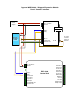
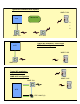
Typical RF installation with repeater WMR-71XX Obstruction ACS 0 1 2 WMR-7211 RPT-5651 Typical RF installation - line of sight! WMR-21XX configuration ACS WMR-71XX WMR-7211 Typical RF installation - ! expansion modules! ! WMR-22XX configuration WMR-71XX WMR-7211 ACS EXP-1000C (2)
! CYPRESS */5&(3"5*0/ 40-65*0/4 WMR-2000 Series! ! ! Wireless Mobile Reader Kit Product Specifications! WMR-2000-V3_SS_1013
! Physical Specifications! ! Handheld Reader -8.25” x 5” x 2” - 1.5 lbs ( with batteries - not included )! Base Unit - 6.75” x 3.75” x 2.00” - 1.
ADDRESS PROGRAMMING ADDENDUM! The handheld units are shipped preconfigured for use with their respective Central Units. One Handheld is designated as "Out Bound" and has the polling address of 0 (zero). Another is labelled as "Inbound" with address 1. And the third handheld is set up as a spare unit with a polling address of 2 (not in the central unit's polling sequence).
! ! ! Take a handheld out of service: 1. Turn the spare handheld on by pressing the power button momentarily 2. Observe the Red Led is on solid. If not, the batteries may need to be replaced or charged. 3. Present the Programming Card labelled Address 2 4. Observe the Red Led wink for 1/2 second indicating the card was read (there is also an audible beep) 5. The Blue Led should stop blinking and remain solid (or stay off) indicating it is no longer in contact with the Central Unit 6.
WMR Channel Programming ( future )! ! ! The New WMR handheld units will provide for field selection of Channel (2 - 14) and Network address ( 0 - 3 ) using programming cards.! ! Address program cards will be used for programming IN and OUT readers.! ! Sample Channel card! ! ! ! ! ! ! ! ! ! ! ! Sample Address cards! ! ! ! ! ! ! ! ! ! ! Additionally the New WMR base units will offer field programing using dip switches.
Routine Maintenance and Trouble Shooting