
Specifications
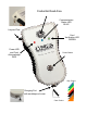
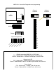

!
R1 Input !
Controls !
Strike on!
Remote
R1 IN
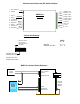
External connections and DIP Switch Settings
1 - 8 to 16 VDC In !
2 - Ground
1 - exp (+)!
2 - exp (-)!
3 - +5 VDC out!
4 - Prog Res 2!
5 - Prog Res 1!
6 - LED In !
7 - D1/Data out !
8 - D0/Clk out
1- Relay 4 N.O.!
2- Relay 4 Com!
3 - Relay 4 N.C.!
4 - Relay 3 N.O.!
5 - Relay 3 Com!
6 - Relay 3 N.C.!
7 - Ground !
8 - Aux out!
9 - R2 in!
10 - R1 in
1
2
3
4
5
6
7
8
Dip switch #4 is ON
-Disable Pullup resistors
Dip switch #4 is OFF
-Enable Pullup resistors
DIP Switch #1 ON !
-Service Mode!
DIP Switch #1 OFF!
-Run Mode
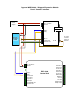
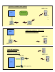
Central Unit Settings
WMR-7211 Central Quick Reference
DC!
Power !
Supply!
Access!
Control !
Panel!
+8 to +16 VDC!
Ground
Diagnostic LED
LED In!
D1/Data Out!
D0/Clock Out#
!
WMR-7211!
Central
Switch!
6 7 8
Wiegand O O O!
Wiegand / No Filter O O X
WMR-7211!
Central