CYPRESS */5&(3"5*0/ 40-65*0/4 SPX-5601! 2.4GHz SPX-5521! 900 Mhz Suprex RF Series Operations Manual Suprex® Reader Extender RF Wireless Interface RPT-5651! 2.
## Cypress Suprex SPX-5000 Series Overview This manual covers the operation and setup of the Cypress Suprex RF SPX-5000 series wireless units. # # Overview # :# The SPX-5000 series of RF Wireless solutions provides a wireless bridge from card readers with gates or door hardware to most access control manufacturers panels. The SPX or Suprex® products include both the remote ( Door/Gate ) unit and the central ( AC Panel ) unit.
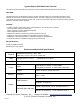
# Suprex® RF Part Numbers Part Number! Description! ! ! SPX-5521 915 Mhz - extender 10000 ft range RPT-5551 ! Interface ! UPC Wiegand or Clock & Data 816684003387 915 Mhz - repeater 1000 ft range N/A 816684003394 SPX-5601 2.4GHz - extender 2000 ft range Wiegand or Clock & Data 816684003219 SPX-5621 2.4GHz - extender 10000 ft range Wiegand or Clock & Data 816684003189 RPT-5651 2.
# # # # # # # # # # # # # # # External connections and DIP Switch Settings 1 - 8 to 16 VDC In # 2 - Ground 1- Relay 4 N.O.# 2- Relay 4 Com# 3 - Relay 4 N.C.# 4 - Relay 3 N.O.# 5 - Relay 3 Com# 6 - Relay 3 N.C.
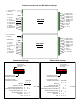
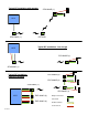
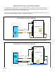
# # # # Central SPX-5000 Series # Quick Reference For Typical Connections # # # # # # DC# Power # Supply# +8 to +16 VDC# Ground Diagnostic LED # # # # # # # # # # # # # # # # # # # # # # # 5 of 17 R1 Input # Controls # Strike on# Remote Access! Control ! Panel! LED In# D1/Data Out# D0/Clock Out# R1 IN # # # See page 10 for other # #strike control options # # # # Remote SPX-5000 Series # DC# Power # Supply# +8 to +16 VDC# Ground Diagnostic LED R1 N.O.# R1 Com# R1 N.C.
# # Typical RF installation with repeater # ACS # # # # # # # SPX-5000C (1) ACS # # # # # # SPX-5000R (1) RPT-5X51 # # # # # Typical RF installation - line of sight # SPX-5000R (1) SPX-5000C (1) Typical RF installation - ! expansion modules EXP-2000R (2) EXP-2000R (3) SPX-5000C (1) SPX-5000R (1) ACS EXP-2000C (2) # # # Wiegand connection# Card reader # EXP-2000C (3) RS-485 multi-drop# Control and I/O 6 of 17
# Cable Recommendations! Belden or equivalent! # # # # # # SPX-1300, SPX-7500 and EXP-1000/2000! # RS-485 connection! # PVC - Belden 9744 - 22 AWG 2 twisted pair, 4,000 feet max.# Plenum - Belden 82741 - 22 AWG 2 twisted pair, 4,000 feet max.# # # # # SPX-1300, SPX-7200, SPX-7400/10, SPX-5601, SPX-5621, SPX-5521, WMR-7211, EXP-1000/2000! # Wiegand, power and LED! # PVC - Belden 9942 or 8777 - 22 AWG 3 pair shielded, 250 feet max.# Plenum - Belden 82777 - 22 AWG 3 pair shielded, 250 feet max.
Cypress Suprex RF Series - Setup and Pre-installation Unpacking:! # # # Remove covers from units and check interior for any shipping damage. Remove any packing material if present.# Inventory any included parts (depending on model) such as antennas, coax cables etc.# Bench Testing:# Before installing the units in the field they should be assembled and tested at a convenient “Bench top” location.
# # # # # # # # # # # # # # # # # # # # # # # # # # # # # # # # # # # # # # # # # # # # # # # # # # # Cypress Suprex RF Series - Indicators and Operating Modes LED Diagnostic Indicator:# # # # The LED Diagnostic indicator provides information on the operational status of the unit.# If the units are not communicating, viewing the diagnostic indicator LED’s may help to determine the # nature of the problem.
# # Cypress Suprex RF Series - # Door Strike and LED I/O # # # # # # # # # # # # # # # # # # # # # # # # # # # # # # # # # # # # To activate the relay on the Remote unit, connect as shown below. These connections can be used to allow the Remote relay to operate a DOOR STRIKE, GATE, or other locking hardware. Refer to following pages in this document for details of each I/O operation and connection.# # There are two relays available for accessory outputs at the Remote end.
# Cypress Suprex RF Series - Door Strike and LED I/O The Cypress SPX-5000 provides additional data channels to support access control hardware such as door strikes, tamper alarms, request to exit status, etc. These signals are sent to and from the Remote and Central units without the need to run additional wiring.# # The accessory control I/O use active low inputs. When the inputs are floating (nothing connected) the associated output will be set to a high level.
# Cypress Suprex RF Series - Relay Controls Relay 4 N.O# Relay 4 Com# Relay 4 N.C. Suprex Central Relay 3 N.O.# Relay 3 Com# Relay 3 N.C. Suprex Central Contact Outputs Contact Outputs Red arrow denotes direction of command signal Suprex Remote Suprex Remote Relay 4 IN Relay 3 IN Input Signal (5Volts DC Maximum) Input Signal (5Volts DC Maximum) Relay 3 functions as an Alarm relay and monitors the condition of the communication link between # the Central and Remote units.
Cypress Suprex® RF Series - Relay Controls # Suprex® Central Suprex® Central Relay 2 IN Input Signal Relay 1 IN Input Signal Red arrow denotes direction of command signal Relay 2 N.O.# Relay 2 Com# Relay 2 N.C. Suprex® Remote Contact Outputs Relay 1 N.O.# Relay 1 Com# Relay 1 N.C.
SPX-XXXX Application Note # Using Supervised Contacts with the SPX-series Extenders # Applies to the following products: SPX-5501, SPX-5601, SPX-5521, SPX-5621, SPX-7400, SPX-7410, SPX-7200, SPX-7500, All RIM series products. # This application note describes the connections necessary to convey supervised contact status over a Suprex® communication link. The configurations described in this app note should apply to most panels that utilize supervised contacts.
SPX-5000 Setup - Using Expansion Modules Before using EXP-2000 Expansion modules with the SPX-5000 system, it will be necessary to perform a short configuration process. This process determines if the 5000 will utilize expansion modules, and if so, how many will be used with the system. Each SPX-5000 link can support up to 2 expansion modules. # # # # # # SPX-5000 units are shipped in the factory default condition.
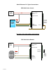
Cypress Suprex Series - Wiegand Expansion Module! Panel “Central” interface DC# Power # Supply +8 to +16 VDC# Ground EXP(+)# EXP(-)# # # # Access! Control ! Panel LED In D1/Data Out# D0/Clock Out 8 to 16 VDC In# Ground 485(+)# 485(-)# +5 VDC Out# Prog Res 4# Prog Res 3# LED Input# D1 Wiegand # D0 Wiegand * 16 of 17 SPX-XXXX ! Central EXP-2000! Central Unit R1 Input # Controls # Strike on# Remote R1 IN RLY4 N.O.# RLY4 Com# RLY4 N.C.# RLY3 N.O.# RLY3 Com# RLY3 N.C.
Cypress Suprex Series - Wiegand Expansion Module! Reader/Door “Remote” interface DC# Power # Supply 8 to 16 VDC In# Ground EXP (+)# EXP (-)# # # # SPX-XXXX ! Remote R1 N.O.# R1 Com# R1 N.C. LED Out# D1/Data In D0/Clock In Card # Reader 8 to 16 VDC In# Ground 485(+)# 485(-)# +5 VDC Out# RLY4 Input (5V)# RLY3 Input (5V)# LED Output# D1/Wiegand# D0 Wiegand * EXP-2000! Remote Unit RLY2 N.O.# RLY2 Com# RLY2 N.C.# RLY1 N.O.# RLY1 Com# RLY1 N.C.