
Specifications

#
of 14 17
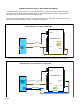
Door
N.C.
Contact
Rex
N.O.
Contact
1K
1K
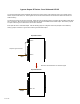
Relay 2 N.O.#
Relay 2 Com#
Relay 2 N.C.#
Relay 1 N.O.#
Relay 1 Com#
Relay 1 N.C.#
Ground #
Aux in#
Not used#
Not used
exp (+)#
exp (-)#
+5 VDC out#
R4#
R3#
LED out#
D1/Data In #
D0/Clk In
Diagnostic LED
8 to 16 VDC In #
Ground
Remote Unit
1K
1K
SPX-XXXX Application Note
#
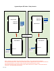
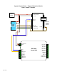
Using Supervised Contacts with the SPX-series Extenders
#
Applies to the following products: SPX-5501, SPX-5601, SPX-5521, SPX-5621, SPX-7400,
SPX-7410, SPX-7200, SPX-7500, All RIM series products.
#
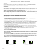
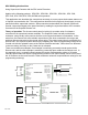
This application note describes the connections necessary to convey supervised contact status over
a Suprex® communication link. The configurations described in this app note should apply to most
panels that utilize supervised contacts. When connected as described, the Suprex® system will
provide a supervised signal to the panel interface by reading the supervised status of the contacts
connected to the Suprex® Remote unit.
#
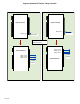
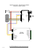
Theory of operation: The Access control panel is looking for a certain value of resistance
connected to the supervised contact terminals. The Suprex® Central unit will provide these
resistance values locally at the panel so that the correct supervised status is maintained. At the
same time, the Remote unit must maintain supervision of the wires connected to the relays and
switches that are connected to the remote access point. The contact supervision is provided by the
Remote unit. The Suprex® system does this by comparing the value of programming resistor at the
Central unit with the resistance seen at the Remote interface terminals. When there is a difference
in the two values, the Relay on the Central unit is activated.
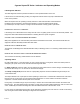
There are two different examples. One example is monitoring a normally closed contact at the
Remote unit, and the other example is monitoring a normally open contact at the Remote unit. In
the examples given, a normally closed contact will require a programming resistor of 1K and a
normally open contact will require a programming resistor of 2K. Other resistor values can be used
but 1K resistors are the most common. Other resistance values will require different value(s) for the
programming resistor(s).
8 to 16 VDC In #
Ground
Relay 4 N.O.#
Relay 4 Com#
Relay 4 N.C.#
Relay 3 N.O.#
Relay 3 Com#
Relay 3 N.C.#
Ground #
Aux out#
R2 in#
R1 in
Diagnostic LED
Central Unit
1K
1K
I1-
I2-
I2+
1K
2K
I1+
exp (+)#
exp (-)#
+5 VDC out#
Prog Res 4#
Prog Res 3#
LED In #
D1/Data out #
D0/Clk out