
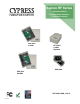
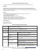
Specifications

#
#
#
#
#
#
#
#
#
#
#
#
#
#
#
#
#
#
#
#
#
#
#
#
#
#
#
#
#
#
#
#
#
#
#
#
#
#
#
#
#
#
#
#
#
#
#
#
#
#
#
of 9 17
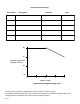
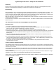
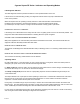
LED Diagnostic Indicator:#
#
The LED Diagnostic indicator provides information on the operational status of the unit.#
#
If the units are not communicating, viewing the diagnostic indicator LED’s may help to determine the #
nature of the problem.#
#
When the Suprex units are operating correctly and have a valid communication channel between#
the Remote and Central units, the Diagnostic indicators on each unit will flash green rapidly #
(2-3 flashed per second) in Service / Config mode and illuminate a steady green in quiet mode.#
#
#
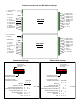
DIAGNOSTIC LED NOT ILLUMINATED:#
#
If the LED(s) are not illuminated on the unit(s) then the unit is not getting power or there is an electrical problem. The
Diagnostic LED’s will be illuminated Red/Green or flashing whenever power is applied.#
#
CENTRAL UNIT FLASHING BETWEEN RED/GREEN:#
#
With power applied and no communication path between the Remote and Central, the Central unit will flash the
diagnostic indicator alternately between Red and Green.#
#
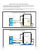
REMOTE UNIT ILLUMINATED RED:#
#
The Remote unit will diagnostic LED will illuminate solid (not flashing) red if it is not receiving communication from the
Central.#
#
REMOTE AND CENTRAL UNITS FLASHING BETWEEN RED/GREEN:#
#
The Central is not Receiving communication from the Remote.#
#
Operating modes:#
#
By setting DIP switch 1 to the ON position, the unit is placed in Setup / Config mode. When the switch position is
changed, cycle power to the unit to make the switch change take effect.#
#
In "Quiet" mode (DIP switch #1 OFF) the units will remain quiet unless there is a status change, and will slowly poll
each other about every 10 to 15 seconds to check the link integrity. #
#
The Setup / Config mode places the units in a rapid polling sequence to allow troubleshooting and setup of the
communication link. #
#
The Suprex RF units use a quiet protocol when operating in Quiet mode. Communication between the Central and
Remote unit only occurs when an event requires data transmission or contact needs to be made to maintain
supervision. The RF channel remains quiet most of the time.#
#
During setup or troubleshooting it may be necessary to observe the communication link between the Central and
Remote units. The rapid polling used in the Setup / Config mode can help indicate whether the units can “See” each
other. Additionally the Central unit Diagnostic LED will indicate Red when communication is lost.#
#
In some cases an optimal mounting location can be selected by operating one of the units on a small 12 volt battery
and moving the location while observing the diagnostic LED indicators.
Cypress Suprex RF Series - Indicators and Operating Modes