ROBOT . HEAD to TOE Product User’s Manual – FD04A Rev2.0 FD04A Rev2.0 4 Channel Motor Driver User's Manual V1.1 Apr 2015 Created by Cytron Technologies Sdn. Bhd.
ROBOT . HEAD to TOE Product User’s Manual – FD04A Rev2.0 INDEX 1. Introduction 3 2. Packing List 4 3. Product Specification And Limitations 5 4. Dimension 6 5. Board Layout 7 6. Hardware Installation 11 7. Warranty 16 Created by Cytron Technologies Sdn. Bhd.
ROBOT . HEAD to TOE Product User’s Manual – FD04A Rev2.0 1. INTRODUCTION FD04A Rev2.0 is an enhanced version of FD04A rev1.0. It is a motor driver board to control unit of DC motor up to 2A for each channel. This revision incorporates several important improvement from older FD04A: FD04A Rev2.0 comes with following features: ● Bi-directional control for 4 brushed DC motor (4 Channels). ● Support motor voltage ranges: 7 - 25VDC. ● Maximum current up to 1.5A continuous per channel. ● 3.
ROBOT . HEAD to TOE Product User’s Manual – FD04A Rev2.0 2. PACKING LIST Please check the parts and components according to the packing list. If there are any parts missing, please contact us at sales@cytron.com.my immediately. FD04A Rev2.0 comes with: ● 1 x FD04A Rev2.0 board. ● 1 x 14 way IDE cable connector. Created by Cytron Technologies Sdn. Bhd.
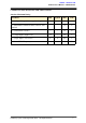
ROBOT . HEAD to TOE Product User’s Manual – FD04A Rev2.0 3. PRODUCT SPECIFICATION AND LIMITATIONS Absolute Maximum Rating Parameter Min Typical Max Unit Power Input Voltage (Motor supply voltage) 7 - 25 V IMAX (Maximum Continuous Motor Current, each channel) - - 1.5 A IPEAK (Peak Motor Current) - - 2.5 A VIOH (Logic Input - High Level) 3.3 - 5.5 V VIOL (Logic Input - Low Level) 0 0 0.5 V Maximum PWM Frequency - - 10 KHz Created by Cytron Technologies Sdn. Bhd.
ROBOT . HEAD to TOE Product User’s Manual – FD04A Rev2.0 4. DIMENSION Created by Cytron Technologies Sdn. Bhd.
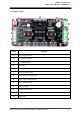
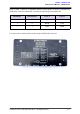
ROBOT . HEAD to TOE Product User’s Manual – FD04A Rev2.0 5. BOARD LAYOUT Label Function A Power toggle switch. B 5V voltage regulator C 7 x 2 IDE Socket D Extra pad E Reverse polarity protection F Power indicator LED G Power supply terminal block H Motor status indicator LED I Motor terminal block J Schottky diode K L298P motor driver L Motor test switch M 3mm hole Created by Cytron Technologies Sdn. Bhd.
ROBOT . HEAD to TOE Product User’s Manual – FD04A Rev2.0 Power toggle switch Switch to ON or OFF FD04A Rev2.0 board. 5V voltage regulator Generates 5V to supply all the transistors and L298P motor driver, include V pin. User can access 5V (at V pin) and use it to supply another circuit. User is prohibited to supply another 5V at V pin. 7 x 2 IDE socket Socket to connect FD04A. Extra pad This is another alternative to access FD04A Rev2.0 control pin instead of using ribbon cable at 7 x 2 IDE socket.
ROBOT . HEAD to TOE Product User’s Manual – FD04A Rev2.0 5.1 Pin Description Figure show the pin orientation of the 7 x 2 IDE socket and extra pad.
ROBOT . HEAD to TOE Product User’s Manual – FD04A Rev2.0 Refer to Table 1, there are 4 individual channels which capable of driving 4 separated DC brush motor, and each channel has 2 control pins (direction pin and enable pin). Enable pin Direction pin OUT A OUT B 0 X LOW LOW 1 0 HIGH LOW 1 1 LOW HIGH User may refers to pin description at the bottom of FD04A Rev2.0 board. Created by Cytron Technologies Sdn. Bhd.
ROBOT . HEAD to TOE Product User’s Manual – FD04A Rev2.0 6. HARDWARE INSTALLATION 6.1 Connecting Power Supply User may connect power supply to the POWER terminal. Please ensure the power supply voltage range within 7 - 25V (refer to product specification and limitation). Make sure the polarity is correct. Created by Cytron Technologies Sdn. Bhd.
ROBOT . HEAD to TOE Product User’s Manual – FD04A Rev2.0 6.2 Connecting to DC Motor User may connect DC motor to the MOTOR terminal. There are 4 MOTOR terminals with label of M1, M2, M3 and M4. Created by Cytron Technologies Sdn. Bhd.
ROBOT . HEAD to TOE Product User’s Manual – FD04A Rev2.0 7.1 Test DC Motor User may manually test the motor by pressing the test switch. Created by Cytron Technologies Sdn. Bhd.
ROBOT . HEAD to TOE Product User’s Manual – FD04A Rev2.0 6.4 Connecting to Microcontroller There are two methods to access the control pins of FD04A R2, which are through IDE connector or extra pads. IDE connector on FD04A R2 is compatible with FD04A. So, for those already bought the PR19, or build any project that uses FD04A Rev1.0, you still can replace it with FD04A R2. *Note: 5V (V pin) from FD04A R2 can supply the PR19 main board. Using IDE connector Created by Cytron Technologies Sdn. Bhd.
ROBOT . HEAD to TOE Product User’s Manual – FD04A Rev2.0 User can solder any suitable header pin on extra pad. Using extra pad Created by Cytron Technologies Sdn. Bhd.
ROBOT . HEAD to TOE Product User’s Manual – FD04A Rev2.0 8. WARRANTY ● ● ● ● Product warranty is valid for 12 months. Warranty only applies to manufacturing defect. Damaged caused by misuse is not covered under warranty Warranty does not cover freight cost for both ways. Prepared by: Cytron Technologies Sdn. Bhd. No. 16, Jalan Industri Ringan Permatang Tinggi 2, Kawasan Industri Ringan Permatang Tinggi, 14100 Simpang Ampat, Penang, Malaysia. Tel: Fax: +604 - 504 1878 +604 - 504 0138 URL: www.cytron.