
4 Channel 5-26V, 3A Brushed DC Motor Controller Datasheet


ROBOT . HEAD to TOE
Product User’s Manual – FD04A Rev2.0
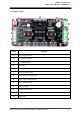
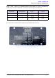
5.1 Pin Description
Figure show the pin orientation of the 7 x 2 IDE socket and extra pad. The function of each
pin is described as below:
PIN
DESCRIPTION
1
Motor 1 direction
2
Motor 1 enable/Speed Control
3
Motor 2 direction
4
Motor 2 enable/Speed Control
5
Motor 3 direction
6
Motor 3 enable/Speed Control
7
Motor 4 direction
8
Motor 4 enable/Speed Control
V
Output voltage 5V
G
Ground
x
Not connected
Table 1
Created by Cytron Technologies Sdn. Bhd. – All Rights Reserved 9