Auto-Calibrating Line Sensor LSS05 User’s Manual V1.2 September 2011 Information contained in this publication regarding device applications and the like is intended through suggestion only and may be superseded by updates. It is your responsibility to ensure that your application meets with your specifications.
ROBOT . HEAD to TOE Product User’s Manual – LSS05 Index 1. Introduction and Overview 3 2. Packing List 4 3. Product Specification and Limitations 5 4. Board or Product Layout 6 5. Installation (hardware) 8 6. Getting Started (from user get the item until using it) 13 7. Warranty (6 months or 1 year) 17 Created by Cytron Technologies Sdn. Bhd.
ROBOT . HEAD to TOE Product User’s Manual – LSS05 1. INTRODUCTION AND OVERVIEW LSS05 (Low cost line sensor bar) consists of 5 IR transmitter and IR receiver pairs. LSS05 is the typically used for embedded system or robots in line following task. LSS05 can be used for either dark or bright line following. Any color with distinct brightness difference is suitable for LSS05. The IR transmitters on LSS05 are pulsed to allow the transmitter to off at certain idle period of sensor.
ROBOT . HEAD to TOE Product User’s Manual – LSS05 2. PACKING LIST Please check the parts and components according to the packing list. If there is any part missing, please contact us at sales@cytron.com.my immediately. 1. LSS05 PCB with every component soldered properly. 2. LSS05 cable connector Created by Cytron Technologies Sdn. Bhd.
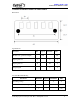
ROBOT . HEAD to TOE Product User’s Manual – LSS05 3. PRODUCT SPECIFICATION AND LIMITATIONS Dimensions Specifications Parameter Min Typical Maximum IR Emission (peak wavelength) Unit 940 nm Input signal, VIH 2 5 V Input signal, VIL 0 0.8 V 5 V Output Signal Absolute Maximum Rating Parameter Typical Maximum Unit Operating voltage 5 V Maximum Current (I/O signal pins) 20 mA 4 cm Sensing distance Minimum 1 2 Created by Cytron Technologies Sdn. Bhd.
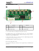
ROBOT . HEAD to TOE Product User’s Manual – LSS05 4. BOARD OR PRODUCT LAYOUT A Top B C F D E Label Function Label Function A Sensor indicator LEDs D PIC16F819 B Calibration button E Power and output signal connector C Mode indicator LED F Power indicator LED A – Sensor indicator LEDs (red) will light up showing that it detects line. B – Calibration button is used to enter different modes. Press once to enter the calibration mode.
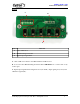
ROBOT . HEAD to TOE Product User’s Manual – LSS05 Bottom C B A Label Function A Pairs of IR sensor B Manufacturing Test Points C Input/output signal label A – Pairs of IR sensor which consist IR transmitter and IR receiver. B – It is reserved for Manufacturing Test Point. Please DO NOT short or connect wire to any of these pins. C –Input/output signal label showing the Power (5V, GND), output signal pins (O1-O5) and calibration signal (Cal.). Created by Cytron Technologies Sdn. Bhd.
ROBOT . HEAD to TOE Product User’s Manual – LSS05 5. INSTALLATION (HARDWARE) Connect to microcontroller 5.1 LSS05 to Mini Mobile Robot Controller (MC40A) Example application of LSS05 is in MC40A. Used as line detection, LSS05 is usually mounted at the bottom of the mobile robot. Created by Cytron Technologies Sdn. Bhd.
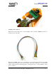
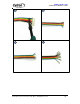
ROBOT . HEAD to TOE Product User’s Manual – LSS05 5.1LSS05 cable connector Figure below shown cable used to connect LSS05 to microcontroller. 2020H-08 connector is used at the end of the cable. Pin pitch for 2020H connector is not standard size for donut board pin pitch. To use LSS05 with donut board, simply cut the end of connector and solder another type of connector like 2510 or 3960 connector. Following figure is showing the step to connect LSS05 to others type of connector.
ROBOT . HEAD to TOE Product User’s Manual – LSS05 1 2 3 4 Created by Cytron Technologies Sdn. Bhd.
ROBOT . HEAD to TOE Product User’s Manual – LSS05 5 6 7 Created by Cytron Technologies Sdn. Bhd.
ROBOT . HEAD to TOE Product User’s Manual – LSS05 Figure below shown LSS05 was connected to donut board. Created by Cytron Technologies Sdn. Bhd.
ROBOT . HEAD to TOE Product User’s Manual – LSS05 6. GETTING STARTED LSS05 need to be calibrated to retrieve the dark and bright value of the surface that it will do the line follow. Every of the IR sensor pairs need to be exposed to the dark and bright surface for it to read the value and save it. LSS05 will save the value in EEPROM, it will retrieve back the data from the EEPROM every time its switch on. Hence, only one time calibration is needed for the same surface and line.
ROBOT . HEAD to TOE Product User’s Manual – LSS05 6.1 Calibration button and signal. The calibration button or the calibration signal (Cal.) has 2 functions. The 1st function is to call for calibration of the line sensor and the 2nd function is to set whether the sensor bar will operate for dark line following or bright line following. 6.1.1 Using the calibration push button Press the push button once to set the sensor bar into calibration mode.
ROBOT . HEAD to TOE Product User’s Manual – LSS05 5V GND 01 02 03 04 05 Cal 6.1.2 Using the calibration signal The calibration signal from the sensor connector can be used to perform exactly the same function as the calibration push button. The calibration signal line requires user to generate falling edges to set for appropriate mode. LSS05 detect how many falling edges to set to appropriate mode. • One falling edge pulse for calibration mode as shown in figure below.
ROBOT . HEAD to TOE Product User’s Manual – LSS05 The usage of the calibration signal pin is optional. The pin (TTL, 5V) can be connected to a microcontroller if user want to use it. The Calibration signal pin has the same functions as the Cal button. Instead of manually pushing the Cal button for the settings of LSS05, user can use a microcontroller to pull down the signal to get into the settings.
ROBOT . HEAD to TOE Product User’s Manual – LSS05 8. WARRANTY Product warranty is valid for 6 months. Warranty only applies to manufacturing defect. Damage caused by misuse is not covered under warranty. Warranty does not cover freight cost for both ways. Prepared by Cytron Technologies Sdn. Bhd. 19, Jalan Kebudayaan 1A, Taman Universiti, 81300 Skudai, Johor, Malaysia. Tel: Fax: +607-521 3178 +607-521 1861 URL: www.cytron.com.my Email: support@cytron.com.my sales@cytron.com.