Page 2 AudioCore Version 8.
Contents Thanks..................................................................................................................................................................... 5 Introducing AudioCore Version 8.40 ................................................................................................................... 5 What’s new in this version? ....................................................................................................................................
Array Control........................................................................................................................................................ 38 Starting Array Control...........................................................................................................................................................38 Setting up Zones ..................................................................................................................................................
Thanks Thank you for taking the time to find out what’s new in the latest version of AudioCore. Please spend a little time reading through this manual, so that you obtain the best possible performance from the software. All XTA products are carefully designed and engineered for cutting-edge performance and world-class reliability. If you would like further information about this software or any other XTA product, please contact us. We look forward to hearing from you in the near future.
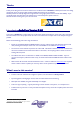
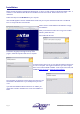
Installation Please note that this software is designed for Windows XP. It will run on older machines under Windows 2000, or NT. It will also run under Windows 98 or ME, but the installation is a little more involved. Please contact us for more information. Follow these steps to install AudioCore on your computer. Insert the CD supplied in the front of all DP-Series manuals into your computer and close the CD drive.
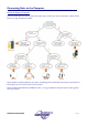
Connecting Units to the Computer Choose the Interface Connection There are several types of remote connection that may be used to connect your units to the computer. Choose the one best for you using the decision tree below. Having decided on the best interface for your system, the following sections deal with the actual set-up and connection of both a single unit, and a network of units to your computer.
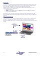
RS232 Interface This interface is fitted as standard to all units and is accessed via the 9-pin D-type connector on the rear of the unit. Note that to connect to a computer’s COM (serial) port correctly, a one-to-one cable must be used, and NOT a ‘null modem’ cable. A ‘null modem’ cable has the ‘transmit’ and ‘receive’ wires swapped over and will not work. The RS232 connection is suitable for distances of about a maximum of 25 feet between the PC and the unit.
RS232 Connection (Multiple Units) If control over multiple units is required, typically the slaves will be set up to run from the RS485 ports on the master unit. Note the incremental ‘ID NUMBER’ setting in the unit’s interface setup. AudioCore Version 8.
Shadow ID Numbers Shadow ID numbers allow extra units to share the same ID and follow the settings of the ‘main’ ID. This is useful for larger systems (for example anything above a 4-way stereo system) where it is only necessary to set up one side of the system, and allow the other unit to track it identically. Using the shadow IDs in this way also reduces the apparent system complexity within AudioCore.
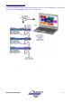
RS485 Connection To use RS485 communication directly from a computer, a master unit must be configured to receive RS485. You must have a suitable RS485 port on your computer, or a converter connected to the serial port in use. This configuration is shown below, along with the required unit setup. Both the converter and the required adapter cables are available from XTA. The adapter is available in a kit, which includes an RJ-45 adapter, the XLR to 9-pin adapter, and the converter itself.
If your laptop or PC does not have a spare serial port (or any serial ports for that matter!), the RS485 converter must be connected through a USB – Serial converter. The RS485 converter that XTA recommend is available in two types – the standard K2, and the more advanced K2-ADE version. Only K2-ADE version will work with USB-Serial converters, as these converters do not support the extra handshake lines used with the standard converter.
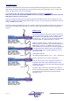
TCP/IP Connection This interface option was added to allow wireless control of units using our Walkabout kit, which offers a complete WiFi solution using standard wireless networking hardware. Please consult the operating instructions supplied with the Walkabout kit for details of how to set up a wireless connection. An abridged version of the Walkabout setup guide is included in Appendix N of this manual.
Setting Up Communications and Going On-line Configuring the Units Themselves For details as to the exact interface operation for each unit, please refer to the operator manual particular to that unit. All units have an interface menu – check that the correct interface has been selected for the type of computer connection to be utilised – RS232 or RS485. Ensure that, no two units are set to the same ID number. It is recommended that the first unit in the chain is assigned ID number 1, the second 2 etc.
Going ‘On-line’ If the remote interfaces have been configured correctly at both the units(s) end and the computer/software end, it will now be possible to go ‘on-line’. This is achieved simply either by choosing Status On Line from the menu bar or by pressing the On/Off line button on the tool bar.
Saving and restoring your system’s settings If you want to store a copy of your system’s current configuration, choose File Save As from the File menu. This file will store all the current settings of all the units, all the memories uploaded, the units’ names (inputs, output, device name), and the device window positions (including if they were minimised or not). To send a pre-configured set-up to a chain of units, select File Open and chose the file you require.
The Device Window and Editing Blocks A window for each unit connected to the system will be available. All types of unit share the same format of window with the following common features. The ‘ID’ number shown in the top left hand corner of the coloured window is the communication channel that the device is using, with the type of device shown opposite this. The signal flow chart shows the processing blocks available for editing and is dependent on the type of device. To edit any block, simply click on it.
Toolbar Guide Working from left to right, the toolbar may be split into groups of related buttons: New System Open System Save System System Options Print System Print Preview Software Version (About…) “What’s This” Help System On/Off Line (Shown On Line) Scan for Units Flash Unit IDs Store Snapshot (System-wide) Recall Snapshot (System-wide) System Mute – All outputs on all units muted! Global Ganging Sets (not available in Version 8.
Menu Tree File New Open Save Save As Start a new system from scratch, or search for connected units Open a previously saved system configuration Save the current system configuration Save the current configuration with a different name Print… Print Preview Print Setup… Print tabular and or curve data for all or part of the system Check the layout of the printed output prior to printing Choose printer and set printer options Options Files Drag Memory Allocation Preferences Background Last file #1 Last
Configuring a Unit The configurations available will depend on the type of unit selected. In the case of a DP448 this screen is equivalent to the ‘Design a Xover’ menu within the unit itself, choosing the type of crossover to implement, and various basic options relating to this.
Channel ganging links controls together so any input or output combination track with the same parameters. Remember that changing the ganging will copy the settings from the lowest channel in any gang to all the others immediately on pressing OK, so be careful when changing this after you have configured your unit! On all 4 Series units, there is an additional function on the Format tab – Clear Settings – this allows various parts of the configuration to be reset to default values.
Editing Input and Output Gains The inputs and outputs on the selected devices are all simultaneously available for editing where gains are concerned. The inputs have mute buttons (active when the button is red), whilst the outputs additionally feature phase reverse buttons. Note that if there are inputs that have not been routed to any outputs their respective gain controls and meters will be hidden.
Editing Delay Settings The delay adjustment tab allows adjustment of the input (base) delays, as well as the output (driver/zone alignment) delays. All input and output delays for the device are shown as text boxes, allowing numerical values to be directly entered. Additionally the values may be nudged, using the spin buttons below the Step Size pane. The smallest step size will depend on the unit type – for DP224/6/6i it is 2.
Editing Limiter Settings The limiter screen permits access to all the output limiters at once, along with real time metering of all input and output channels on the selected device. The threshold above which limiting may take place is set in the appropriate ‘Level’ text box at the top of the output channel section. Note that only 4 Series units have the additional Clip Limiter settings, and have higher resolution metering.
Editing Graphic Equaliser Settings Each input channel’s graphic equaliser is displayed with a response curve that shows just its contribution to the signal path. Changing the response type, or ‘Q’ shape will be reflected in the response shown. The ‘GQ600’ response has a ‘Q’ that varies with cut/boost applied – wider ‘Q’ at lower values of cut/boost, resulting in a smoother response when smaller amounts of EQ are added.
Editing EQ and Crossover Settings The equalisation and crossover screen will vary slightly dependant on the device that is currently selected. However, the principles of operation are identical in all cases. The most important areas of the screen are the frequency response curve which may be edited simply by dragging portions of the curve to produce the desired response, and the direct filter control section just above this.
Modifying Curve Dragging Behaviour Several options exist to adapt the way the curve dragging feature operates. These are accessed by selecting File Options from the menu bar or by pressing the Options button on the toolbar. The four options are: Enable Curve Dragging – if unticked the curve appears just as a frequency response representation, and is not interactive.
Editing with Direct Filter Control The direct filter control allows precise details to be entered via the filter list. Double clicking on any filter parameter will display a small window with all the parameters for that filter available for editing. Remember that the filter has to be bypassed before its type can be adjusted – the drop down list will remain yellow until this is done. It is possible to directly step through each band in turn by using the double arrow buttons at the bottom of the window.
Shadow EQ Curves A further enhancement to the response curves available on the input and output EQ tabs is the addition of the shadow EQ display. When a filter is selected for adjustment, its contribution to the overall response for that output is shown as a grey shadow fill on the background. This is useful for indicating when a band’s contribution to the output will be inaudible, for example when a parametric is set to a frequency above the crossover point on that output.
Phase Response Due to the enhanced filter set available in the 4 Series, including phase and all pass filters, a phase response has been added to the filter adjustment tabs in this version of AudioCore. The +18dB line on the level axis represents a phase shift of +180°, with –18dB being -180°. It is selectable by right clicking on the frequency response curve as below. There are three settings: Off – no phase response shown; Active – only the currently selected filter’s phase response is shown.
Response View Range Adjustment It is now possible to select a “zoomed out” level scale to show the roll-off of crossover filters more clearly, as the 4 Series units can provide much sharper slopes than were previously possible with the DP224/6/6i. Roll-offs well above 48dB are achievable - please see the section entitled “Enhanced Filter Set Usage” on page on page 48 for details of this.
Copying and Pasting Features Graphic EQ settings and many other parts of a unit or channel’s data may be copied and pasted into other parts of the system, subject to certain restrictions. Starting with the graphic EQ settings, a right click on the response curve will bring up a floating menu allowing the fader settings (and response/bypass state) to be copied.
Memory management and access The memory management and access features in this version of AudioCore have been completely revised to allow individual unit memory store and recall, as well as snapshot store and recall across the entire system. In addition, the handling of the different memory types (Input and Crossover in DP224/6/6i, with additional Graphic memories in the 4 Series) has been improved to make it much simpler and easier to understand.
When storing any EQ combination, all memories are shown; when recalling, only those of that particular type, or memories containing at least those elements will be listed. In this example, choosing to recall memories of type “Input and Xover” will show numbers 01 and 11 in addition to 02 and 09 which contain just Input and Xover settings as it is possible to recall just these parts out of another combination memory.
Recalling a snapshot will perform a system-wide memory recall. Initially, only complete snapshot memories will be shown in the list of available locations, but ticking “Show All” will show the locations of all memories that have something stored in them somewhere on the system. In this example, only location 01 would be shown initially, as it is the only location with a full snapshot stored. If “Show All” is ticked, the other locations are displayed, but greyed out.
Security Features and Password Lockout The software supports two levels of password-protected security – User and Supervisor. Supervisor is the higher access level, allowing all parameters to be locked, whilst User level permits any parameters not locked by the supervisor to be locked. The supervisor also has the ability to clear the users password. To begin the locking process, press the button on the toolbar. This will display a dialogue prompting for a password.
Note that unless the system is on-line, no prompt to send lock status to units will appear. Once locked, each unit will display a confirmation message on the bottom line of its display, and the software will change all locked parameters to grey text boxes. Considering the output equalisation screen previewed earlier, it will change to be displayed as shown below.
Array Control Due to the powerful features available within Array Control, it is advisable to read this section carefully before attempting to use this feature, especially in a live situation. Array Control opens up the power of addressable zones for the control of large systems, configured exactly as the user requires. Outputs may be included in as many zones as required allowing effective sub-zones to be created along with more ‘global’ zone configurations.
For the purposes of this description, 14 units are connected to the system, and are identified above by the colour-coded available unit buttons, with ID numbers as shown. Hovering over the buttons will display the respective unit’s name. Note the pair of large buttons on the right hand side – currently the ‘SETUP’ mode is active. The other mode, ‘LIVE’ mode, is designed to be used during a show.
Setting up Zones A total of 28 zones are available, arranged in groups of four, accessible using the green ‘Zone Group’ buttons. Zone groups may be named by pressing the ‘Name Zone Groups’ button. To set up a zone, start by assigning the required outputs from any unit to the zone. This is achieved by selecting the unit by pressing its button. This will display the device zone assign window shown below. In this example the eight outputs on the selected DP448 are displayed.
Control and Details of Zones Referring to the master window, pressing one of the zone group buttons will display a zone control window with four zones available at any time. The name of the zone appears at the top of the strip, followed by its gain control and “Set 0dB” button, gain readout, mute button, and zone solo button. Additionally there is a 'Zero Zone’ function which temporarily removes Array Control’s contribution to all the outputs in the zone.
Array Control Options As mentioned earlier, ‘SETUP’ and ‘LIVE’ modes may be thought of as equivalent to supervisor and user lock levels in the normal Audiocore software.
Miscellaneous Tools and Functions Scan System This is available under the ‘Status’ menu. When selected a window will appear allowing all possible addresses on the system to be scanned for the presence of any units. Any found will be reported with their model number and current software version. The example here shows that the first seven IDs are present. Note that only the first 32 ID numbers are scanned, even though 4 Series units support ID numbers up to 128.
Temperature Check Selecting this from the ‘Tools’ menu will display a window similar to the ‘Scan System’ function described on the previous page. The units on the system report back three readings – the first is the current temperature, the second (in brackets) is the maximum this session, with the third being the maximum temperature ever reached.
External MIDI Recall Audiocore can be configured to respond to externally generated MIDI ‘program change’ messages received on a MIDI port, selected from the Snapshots External MIDI Recall option. Any program change message received will trigger a snapshot memory recall to the whole system, as long as the program change data is within range. Background Image Option Selecting File Options and the ‘Background’ tab allows selection of a ‘wallpaper’ image for the parent window of Audiocore.
Refresh Button The refresh button, found on the toolbar at the top of the screen, allows the software to pull in all the current settings of the connected settings at any time, without having to go off-line and on-line again. Pressing this button (which will be greyed out until the system is on-line) will display a window showing the brief process of re-synchronising the system.
Smart Tips Smart Tips display pertinent information about any processing block as displayed in the device window, without the need to click and open any additional windows. Just hovering the mouse pointer over the block will bring up the smart tip, as shown below. This is the smart tip for the crossover section of a DP448, showing the crossover frequencies currently in place.
Enhanced Filter Set Usage Producing steeper crossover roll-offs than 48dB Using a combination of the high or low pass filters and the elliptical parametric filters, much steeper crossover slopes can be realised than ever before. The following example shows how to produce a low pass filter with a roll-off in excess of 70dB/Octave. This technique can be used with high pass crossover filters as well. Select a 48dB low pass filter, and set the frequency as required.
Producing a flat-topped filter response. To create a flat-topped EQ filter response such as that shown to the left, use two EQ bands, BOTH configured as low shelves. For an overall BOOST, set the Lower frequency filter to BOOST the desired amount, and the Upper frequency filter to CUT by the same amount. The example has the filters set at: PEQ1: Low Pass 99Hz @ -10dB, Q = 0.75 PEQ2: Low Pass 2kHz @ +10dB, Q = 0.75 Varying the ‘Q’ affects the slope of the response – higher values will cause overshoot.
Printing from AudioCore AudioCore can produce a tabular and graphical printout of any part of your system. This is set up via File Print… from the menu, or with the shortcut button on the toolbar. Either will display the options window shown here. The options available allow the unit (or all units) to be chosen for printing and whether to print all the uploaded memory settings.
Appendix 1: Walkabout Kit and WiFi Set-up Guide Introduction XTA have spent a considerable period of time searching for a reliable, straightforward solution to creating a wireless system that can interface with our units. The obvious choice of standard network is to utilise the ‘Ethernet’ system as utilised by computer and control systems worldwide. We have developed a new version of AudioCore to work with local area networks (LANs) and wireless local area networks (WLANs) using the TCP/IP protocol.
Upgrading unit software Note that this procedure can only be done one unit at a time – it is recommended that the unit being updated is disconnected from any RS485 network until the procedure is complete. Connect the unit to upgrade to a spare COM (serial) port on your PC or laptop. The serial cable must be a “one-to-one” cable and NOT a null modem cable. This is because a null modem cable has “transmit” and “receive” wires swapped, and so will not work.
Installation Set up the Netgear card first: Install the Netgear driver for the WG511T using the supplied Netgear driver disk BEFORE plugging the card into your PC or laptop. Follow the instructions on screen. Now plug the card in – Windows should recognise it and load the drivers as required. If, after installation, Windows then asks to load drivers itself, or reports new hardware found, it is now safe to follow these instructions. If a warning is displayed select ‘Continue Anyway’.
Set the Netgear Card IP Address Whilst Windows will automatically assign the Wi-Fi card an IP address, our experience has shown that this must be changed manually to ensure correct operation. Here’s what to do… From your Windows desktop, click start, then ‘Control Panel’ to display… The ‘Network Connections’ icon is already highlighted here. Double click on the ‘Network Connections’ icon to display the list of network connections in place on the computer.
The item listed (and highlighted) here that needs to be checked is the ‘Internet Protocol’ item – select it and then click on the ‘Properties’ button to reveal the window shown below, which gives access to the actual IP address etc. used by the Wi-Fi card. Make sure that ‘Use the following IP address’ is selected and the IP address is similar to that shown (i.e. starting with 192.168.). If it is an auto-allocated address (typically of the format 169.202.x.x), change it to one beginning 192.
Search for and Establish a Wireless Link to the Wiser On your Windows desktop, double click on the Netgear Wi-Fi icon in the system tray beside the clock. This will display a window as below. Click onto the second tab on this window, ‘Networks’, to display… Press the ‘Scan’ button and the card will try to find any available Wi-Fi networks in range.
Setting up AudioCore to work with the Wiser You will need to install AudioCore version 8.00 or greater on the PC to be used with the wireless system. Start AudioCore as normal and then choose the menu Remote TCP/IP. The window below will be displayed. Pressing the “Test Connection” button should display a message saying “Connected to TCP/IP!” and the address/port number. Assuming this works, you should now be able to go on-line, and use AudioCore as normal.
Useful Operation Hints Tablet Features: Some tablet PCs will have a feature whereby holding down the stylus acts like a right mouse click. You may want to turn this feature off, as scrolling can be difficult. Please refer to your specific tablet PC operating manual for details. Connection Problems: Try experimenting with the location of the PC relative to the Wiser – sometimes the case of the computer can shield the radio link.
Setting up the Wiser…using a unit (4 Series/226/224 only) It may be necessary to change or check the settings stored in the Wiser to aid trouble shooting. This section explains how to access and adjust the various parameters. From the default screen press MENU and use BACK and NEXT to navigate to <- MAIN Menu: . . . . . . -> Interface SubSub-Menu and press ENTER then NEXT to display <- INTERFACE Menu: . . .
WEP Encrypt: 64Bit* Choose between ‘None’, ’64 Bit’ , and ‘128 Bit’ using the FREQ control. “Wired Equivalent Privacy” or WEP encryption is a method of making a wireless network more secure by encrypting the data transmitted using a ‘Key’ that both ends of the system must know to access the data. Working out what IP addresses are available on a WLAN is relatively simple, so allowing anyone in the vicinity to potentially gain control over any connected devices.
Setting up the Wiser…using a PC This section explains how to configure the Wiser using a PC, instead of plugging it directly into an XTA processor. This might be useful if you don’t have a unit available, but need to confirm the network and communication settings of the Wiser.
Troubleshooting Please ensure that any changes to your computer’s network settings, the Wiser settings, or the connected XTA processors’ interface setting take place with AudioCore OFF-LINE. Firstly, check again to see if the Netgear card has been able to find anything – see page 56 for details. If there are still connection problems, it might be worth checking to see what IP addresses are being used by any Ethernet devices connected to the computer.
Walkabout Kit Frequently Asked Questions My laptop has Wi-Fi built in – can I use this? The XTA Walkabout pack has been specifically designed for use with the supplied Netgear Wireless card. It is possible to configure an internal Wi-Fi system to communicate with the Wiser. XTA does not recommend this approach, and we cannot guarantee correct operation. However, if you wish to use the internal Wi-Fi, the required settings are on page 55 of this manual.
Appendix II: Remote Interface Guide This document outlines all the currently available interface combinations and options available for remote control of DP series processors. Please use the decision tree to help you choose the correct interface for your application. If you would like to discuss the options with us, please feel free to email us. Page 64 AudioCore Version 8.
INT-232 – Serial Cable What is it? It is a lead to connect directly from the “External” port on the back of a unit to a 9-pin (Serial) port on a PC or laptop. What is included? One 9-pin male to female serial lead, approximately 2 metres long. When should I use this? If your first unit is no more than 25 feet (approx 7.5m) from the computer, and you have a spare 9-pin COM port available, this is the simplest and cheapest way to get connected.
INT-485 – RS232 to RS485 Conversion Kit What is it? A kit to convert the standard 9-pin RS232 serial connection from a COM port on a PC into a balanced 2-wire + shield connection on male XLR. What is included? 1 x KK Systems “K2” RS232-RS485 converter; 1 x 9 pin D-type male to 3 pin XLR male adapter; 1 x 3 pin female XLR to RJ45 adapter cable.
USB-232 – USB to Serial Converter What is it? An electronic adapter that intelligently converts a USB interface into a standard 9-pin serial COM port. What is included? 1 x Aten “UC232a” USB to Serial adapter; 1 x INT-232 Serial Cable; 1 x Driver disk; 1 x Manual. When should I use this? Newer PCs and laptops tend to not include traditional 9 pin serial connections any longer, and AudioCore works through a serial port.
USB-485 – USB to RS485 Conversion Kit What is it? A combination of a USB to serial interface and RS232 to RS485 converter to provide direct balanced 2 wire + shield connection. What is included? 1 x Aten “UC232a” USB- Serial adapter with driver disk & manual; 1 x KK Systems “K2-ADE” RS232-RS485 converter; 1 x 9 pin D-type male to 3 pin XLR male adapter cable.
INT-WLAN – Walkabout Kit : WiFi Conversion Kit What is it? A combination of a WLAN to serial interface and a high power wireless PCMCIA card to provide a remote connection using standard WiFi/WLAN 802.11b technology. What is included? 1 x OTC Wiser 2400 WLAN / WiFi to serial converter; Serial cables to connect Wiser to unit or PC for programming; Power supply for Wiser; Netgear WG511T WLAN Card; All required setup software and manuals supplied on custom CD.
OPT-GPI – General Purpose Interface Kit What is it? An interface card that replaces the standard RS232 card for the DP224/6/6i to add closed contact memory recall facilities. What is included? 1 x RS232/GPI interface card; 1 x 15 way D-type to 9 way D-type adapter; 1 x 15 way D-type plug & shell; Manual and fitting instructions. When should I use this? If remote change of memories is required, without involving a PC or other electronic device.
Hints and tips about using external interfaces Always read the manual supplied with the unit for the most detailed information regarding the setup and use of external remote interfaces. In the case of special or older interfaces such as MIDI or LAN to serial converters (for example the MOXA N-port Express) please feel free to email tech@xta.co.uk. A few things worth remembering about using the RS232 and RS485 interfaces in general: Maximum recommended cable length for RS232 is 25 feet or 7.5 metres.