
User`s manual


0º
1º
2º
4º
5º
10º
9º
7º
8º
6º
3º
0º
1º
2º
4º
5º
10º
9º
7º
8º
6º
3º
VARIANT 18
AX-V25
W
ARNIN
G
:
W
EIGH
T
LI
MIT 6
UN
I
T
S
15º
14º
13º
12º
VARIANT 18
AX-V25
WA
R
NI
N
G:
W
E
IG
H
T
L
I
MI
T
6
U
NIT
S
15º
14º
13º
12º
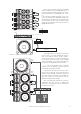
variant 112A
variant 25A
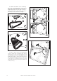
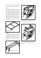
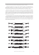
In order to fly the units, the connecting link
must be rotated until the desired splay angle is
reached first (1). Then the quick release pin must
be introduced into the pin hole labeled with the
desired splay angle (2). The box will be flown from
the rotating point located in the top box as shown
in the figure (3), and finally the lower box will be
secured by introducing one more quick release pin
in the top box (4).
4
1
2
3
variant 112A
variant 25A
1
2
3
4
16
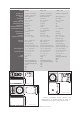
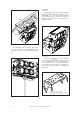
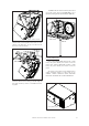
To facilitate the insertion of the connecting
links in the corresponding slot of the top box,
each angle has an associated pin hole which is
labeled and located on each side of the box.
Highly resistant 6mm quick release pins with a
ball safety lock are used set the angles.
Manual del Usuario / variant / User’s Manual