MAX12 Data Sheet
Safety precautions Never stand in the immediate vicinity of loudspeakers driven at a high level. Professional loudspeaker systems are capable of causing a sound pressure level detrimental to human health. Seemingly non-critical sound levels (from approx. 95 dB SPL) can cause hearing damage if people are exposed to it over a long period.
MAX12 MAX12 is a 2-way floor monitor system and uses a 12/2 coaxial driver combination with a passive crossover. The driver design allows the use of a compact, low height cabinet. MAX12 can be driven actively or passively. Coaxially mounting the 2 HF and 12 LF drivers creates a very compact single driver whilst retaining the benefits of separate magnetic assemblies.
Only operate MAX12 loudspeakers with a d&b P1200A mainframe fitted with ampMAX or AMP-L controller modules or with an d&b E-PAC in linear configuration. As an alternative other high quality power amplifiers may be used, provided their output power does not exceed 500 watts into 8 ohms and an additional subsonic filter is used (25 Hz with 12 dB/octave minimum), otherwise there is a risk of damaging the loudspeaker components.
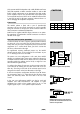
Operation with P1200A and ampMAX module INPUT A AMP A 1+ 1 2+ 2 OUT A INPUT B AMP B 1+ 1 2+ 2 OUT B P1200A with ampMAX, passive mode INPUT A Active Crossover Lo Hi INPUT B AMP A 1+ 1 2+ 2 OUT A AMP B 1+ 1 2+ 2 OUT B P1200A with ampMAX, active mode ampMAX is a two-channel controller module occupying both slots of a P1200A mainframe. The combination of P1200A and ampMAX allows MAX and MAX12 loudspeakers to be driven passively or in 2-way active mode.
LFC switch and indicator When MAX12 cabinets are used without an active subwoofer selecting LFC, Low Frequency Compensation, extends the low frequency response of MAX12 cabinets down to 75 Hz. The yellow LFC LED illuminates. In active mode only the channel A LFC switch is functional. IS/GR indicators These indicators give a three stage indication of ampMAX signal levels. − Input Signal Present (green) illuminates when the signal presented to the controller input exceeds a -36 dBu threshold value.
AMP-L module switches CUT switch and indicator Set to CUT, a high pass filter with a 130 Hz cut-off frequency is inserted in the controller signal path. The yellow CUT LED illuminates. MAX12 is now configured for use with d&b C-Series active subwoofers. REMOTE LO IMP 1234 DELAY ON REMOTE LO IMP ON ON 1 2 3 4 5 6 Operation with E-PAC To drive MAX12 cabinets the E-PAC has to be configured to LINEAR mode.
Dispersion characteristics Due to the conical coverage pattern of the coaxial driver design, the horizontal and vertical dispersion characteristics of MAX12 are largely identical (slight differences which do occur are attributable to the asymmetric cabinet shape). The diagram below shows dispersion angle versus frequency plotted using lines of equal sound pressure (isobars) at -6 dB and -12 dB.
Technical specifications MAX12 system data, passive setup Max. sound pressure (1 m, free field) with P1200A........................................... 132 dB Max. sound pressure (1 m, free field) with E-PAC ............................................. 130 dB (SPLmax peak, pink noise test signal with crest factor of 4) Input level (SPLmax) ................................................................................................. +13 dBu Input level (100 dB-SPL / 1 m)..................................
d&b audiotechnik AG, Eugen-Adolff-Str.