
Specifications


Controller settings
For acoustic adjustment the functions CUT, HFA, HFC and CPL can be
selected.
CUT circuit
Set to CUT, the T10 low frequency level is reduced. The T10 is now
configured for use with the T-SUB or other d&b active subwoofers.
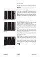
HFA circuit (T10 PS setup only)
-5
0
5
10
-10
-15
-20
-25
-30
20
100 1k 10k
20k
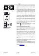
Fig. 5: Frequency response correction of
HFA circuit
In HFA mode (High Frequency Attenuation), the HF response of the T10
system is rolled off. HFA provides a natural, balanced frequency
response when a unit is placed close to listeners in near field or delay
use.
High Frequency Attenuation begins gradually at 1 kHz, dropping by
approximately 3 dB at 10 kHz. This roll-off mimics the decline in
frequency response experienced when listening to a system from a
distance in a typically reverberant room or auditorium.
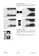
HFC circuit (T10 Arc/Line setups only)
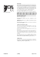
Fig. 6: Frequency response correction of
HFC circuit
Selecting the HFC (High Frequency Compensation) circuit compensates
for loss of high frequency energy due to absorption in air when
loudspeakers are used to cover far field listening positions.
The HFC circuit has two settings (HF1, HF2) for different distance ranges
the cabinets have to cover. The settings should be used selectively, only
for those cabinets covering the respective distances, HF1 for distances
larger than 25 m (80 ft) and HF2 for distances larger than 50 m
(160 ft).
The compensation is adjusted for a typical relative humidity of 40 %.
With lower humidity the absorption by air increases therefore the
distances where the respective HFC setting provides a correct
equalization are shorter than indicated above.
Using the HFC function provides the correct sound balance between
close and remote audience areas, whilst all amplifiers driving the array
can be fed with the same signal.
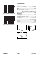
CPL circuit
Fig. 7: Frequency response correction of
CPL circuit
The CPL (Coupling) circuit compensates for coupling effects between the
cabinets; these effects increase as the length of the line array is
extended. CPL begins gradually at 1 kHz, with the maximum attenuation
below 400 Hz, providing a balanced frequency response when T10
cabinets are used in arrays of four or more. The function of the CPL
circuit is shown in the diagram opposite and can be set in dB
attenuation values between –9 and 0, or a positive CPL value which
creates an adjustable low frequency boost around 65 Hz (0 to +5 dB).
Note:
Make sure that all cabinets within the line array are operated
with the same CPL setting.
T10 Manual (1.0 EN) Page 6 of 10