TI 323 (Version 6.
General Information Technical Information TI 323 Version 6.0E, 03/2003, D5323.E.06 © by d&b audiotechnik AG 1995-2003; all rights reserved. The information presented in this document is, to the best of our knowledge, correct. We will however not be held responsible for the consequences of any errors or omissions. Technical specifications, weights and dimensions should always be confirmed with d&b audiotechnik AG prior to inclusion in any additional documentation.
C-Series A modular concept The d&b audiotechnik C4 system has been specifically optimized for flexible, modular array configurations and high sound pressure levels. Applications range from professional touring industry use and large scale sound system installations, down to single cabinet set ups requiring narrow dispersion over a wide frequency range with minimum dimensions.
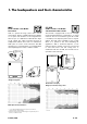
1. The loudspeakers and their characteristics MAX C7-TOP 85 Hz -18 kHz / 133 dB SPL* 60° conical MAX is a passive full range system with a 15"/2" coaxial driver. MAX is available with flying studplates as an option and therefore can be integrated into flown set ups as a dedicated C4 downfill. The shape of the cabinet also allows horizontal arraying of multiple MAX cabinets when used as a stacked near field system.
C4-SUB 50 Hz - 150Hz / 133 dB SPL* The C4-SUB uses a 18" driver in a compact bandpass horn design. As a part of the C4 system, the C4-SUB is designed to be used with the C4-TOP. C7-TOP dispersion characteristics** C4-TOP 150 Hz -18 kHz / 138 dB SPL* 35° horizontal x 35° vertical The C4-TOP uses a 12"/2" driver combination in a coaxial horn-in-horn design. The shape and acoustic design (the use of CD horns) of C4-TOP cabinets enables them to be arrayed for increased coverage.
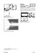
B2-SUB 32 Hz - 68 Hz (Infra mode) / 136 dB SPL* 37 Hz - 125 Hz (Standard mode) / 139 dB SPL* The B2-SUB uses two 18" drivers in a bandpass horn design. In the examples discussed in this TI the B2-SUB is used as an infrabass enhancement for C4 systems (combined with C4-SUBs) and exclusively used in Infra mode. Dimensions in mm [inch] Weight (incl. wheels): 71 kg/156 lb Dimensions in mm [inch] Weight (incl.
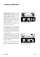
2. System amplification Suitable for use with all d&b C-Series systems, the P1200A mainframe (2 x 600 W / 4 ohms) has two front panel slots to accommodate one or two loudspeaker specific controller modules. In the case of the C4/C7 loudspeakers one channel of a P1200A mainframe can drive up to two cabinets.
3.
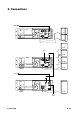
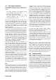
3.1. Line signal connection Line level signal wiring needs much more care than most people believe. In total there are three major factors to consider: − The output impedance and maximum output current capability of the driving device. − The length of all connecting cables. − The total capacitance between the signal conductors (between pins 2 and 3 of corresponding XLR connectors).
3.3. Mains power supply requirements Power consumption of amplifiers is dependent on many factors including load impedance, signal level and signal characteristics (speech, music). A key factor in estimating amplifier power consumption is the crest factor (CF) of the applied signal. The crest factor is a measure for the ratio of peak to RMS voltage of a signal.
4. Acoustical parameters 4.1. Power and bandwidth The C4 system (C3, C4-TOP and C4-SUB) is a flexible modular sound reinforcement system.
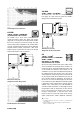
One can easily see, that the narrow dispersion cabinets give greater throw and higher levels towards the far field, but are compromised by uneven near field coverage. Sound pressure coverage of 90°x50°, 60°x40° and 35°x35° system Speech intelligibility is also influenced by the variations in loudspeaker coverage. The second illustration is a plot of the Speech Transmission Index (STI) over the listening area used in the previous illustrations.
4.4.4. Comb filter effects With more than one system per side care has to be taken to minimise the audible influence of the comb filter effect. An unavoidable problem with multiple sound sources, this effect creates a very uneven frequency response with audible peaks and cancellations due to interference across the coverage area.
horizontal dispersion while still radiating a huge amount of LF energy vertically. Vertical arrays behave more practically; they maintain a broad horizontal dispersion while narrowing the vertical pattern. A vertical array puts more energy into standard audience areas than a horizontal line of subwoofers. 4.4.6. Rule of thumb Doubling the number of subwoofers per side will give an additional 6 dB in the low end.
6 Due to the increasing speed of sound at higher temperatures the wavelength will increase (see chapter 5. Sphere or Line?). According to Snell's law the direction of the wave will bend depending on the thermal layers. dB 4 2 If the warm layer is below the cold layer the wave will bend upwards.
5. Sphere or line ? This chapter investigates the differences between spherical and line sources. 5.1. As any loudspeaker has a maximum SPL capability, it maybe necessary to use a quantity of loudspeakers in order to increase the SPL over greater distances. Spherical sources An ideal spherical source is an infinitely small point. Energy radiated from such a point source is distributed spherically.
5.2. Line Sources Line sources are nothing new; in the 50s it was the only economical solution to build loudspeaker systems that provided a specific directivity in a defined frequency range. Without being aware, this technology is often used today to increase the directional behaviour of loudspeaker arrays. The ideal line source is an infinitely long, continuous radiator.
5.2.2. Finite line arrays The length of an array has a large impact on its properties, and due to the finite length of an array the initially cylindrical wave transforms into a spherical wave. This near field/far field transition radius is dependant on the length of the array and the frequency being produced. This radius can be calculated using the following rough formula: l.f 2.
5.2.5. Signal tuning Due to their frequency dependant coupling, curved or J-shaped line arrays require a set up related filter. The reason for this can be explained by considering the wavelength. Coherent coupling occurs when the transmitted wavelength is larger than the radiating source. It is easy to see that everywhere in the audience area the entire array combines to provide the lower frequencies, whilst at higher frequencies only a single source provides energy at any point in the listener area.
6. System design 6.1. Basic planing The first consideration is the combination of horizontal and vertical dispersion angles needed to cover the audience area from specific positions. These positions should be chosen so that the system can give an acoustic orientation towards the stage for as many listeners as possible, while avoiding directing energy at close boundaries or recessed areas. 6.1.1. Step 1: First, the total horizontal coverage angle has to be defined.
Referring to set up examples 8 or 9, described later in chapter 9, a modification of the column for sector 1 could be SUB-SUB-C3-C3-SUB-C4 (from top to bottom), the other columns stay as shown. 6.1.3. Sidefills, backfills, downfills and frontfills Additional systems are needed to cover critical areas such as directly in front of a stage, or side seating tiers. For these areas it is essential to maintain total system integrity and sound character.
6.2. Arraying C3 and C4 cabinets 6.2.1. Vertical array of C3 cabinets A vertical array of C3 cabinets produces a precisely shaped wave front following the mechanical arrangement of the cabinets. The cutoff at the upper and lower limits of the vertical dispersion of a C3 column is very sharp, and therefore precise aiming is absolutely essential to address the desired audience area.
The configuration of any array should be thoroughly adapted to the actual venue room acoustics and requirements. In order to keep diffuse sound low, the total coverage angle should only be as wide as necessary to cover the audience area. C3-CO C3-CO Array EQ Input signal 6.2.4. Operation with C4-SUB and B2-SUB To extend the C3 frequency response C4-SUBs should be used. Forming columns of SUB cabinets improves efficiency and vertical directivity at low frequencies.
7. Rigging concept and devices The d&b flying system provides flexibility for scaling a complete C3/C4/C7 sound reinforcement system. The flying system is designed to aim and position the loudspeaker cabinets in a way that ensures an optimized acoustic result. All d&b flying hardware is Type Approved to the German safety regulation BGV C1. 7.1. 7.1.3. Ratchet strap The ratchet strap is used to set the vertical angle of the loudspeaker column. It is not a load bearing component in the whole assembly.
7.2. d&b flying hardware / cradles 7.2.1. d&b Installer The Installer is a modular flying system mainly for permanent installation or touring use where the setting does not change from day to day. The huge variety of different parts enables the user to create any configuration, starting from a single column up to clusters providing 360° of horizontal coverage. Every column can consist of up to 8 cabinets and a MAX downfill.
8. Planning tools To accelerate the planning of an array the advanced functionality of the TransCalc and InstallCalc spreadsheets can be used. These spreadsheets are available for 2 to 6-wide Transformer set ups and for 2 and 3-wide Installer set ups. 8.1. Hardware settings Depending on the array configuration, TransCalc and InstallCalc calculate the mechanical settings of the cradle.
8.5. Loudspeaker aiming As an enhanced planning aid TransCalc and InstallCalc are able to calculate the aiming of the individual TOP cabinets towards the listener planes. This is very important when using C3s in the array, due to their precisely shaped wave front. Three sections can be defined, the floor area, side and rear tiers. Whether the audience is sitting or standing can also be defined. According to chapter 6.
9. Examples Positioning and placement of the cabinets next to each other and relative to the audience needs careful attention in order to achieve the best performance of a loudspeaker system. Some major issues have been explained above, the following section illustrates examples of standard applications. All drawings show PA left, viewed from front of house. These examples are guidelines for a final system design.
9.3. Example 3: 9.4. Example 4: 16 x C4-TOP, 16 x C4-SUB, 4 x B2-SUB, 8 x P1200A with mixed C4-TOP/C4-SUB controller modules and 4 x A1 with a B2 controller module. This is a 6-wide set up for arenas with side seating tiers and provides 150° of horizontal dispersion. It can be easily adapted to specific situations. The inner columns include long throw and floor coverage. The SUB column is used for increased low frequency throw.
9.5. Example 5: This example shows a small flown array employing 2 x C3 for the far field (approximately > 25 metres/ 82 ft) with a 40° horizontal dispersion. The C4-TOPs provide an 80° horizontal dispersion in the near field, and 4 x C4-SUBs provide headroom and vertical directivity at lower frequencies. For the total system B2-SUBs and ground stacked near field loudspeakers would be added.
9.7. Example 7: 6 x C3, 4 x C4-TOP and 10 x C4-SUB are used in this medium sized array. The C4-SUB arrangement provides the level distribution and power to cope with the C3/C4-TOPs. The SUB column 2 delivers a high vertical directivity, whilst the SUB cabinets in columns 1 and 4 increase the horizontal directivity to the far field. Two to four ground stacked B2-SUBs and additional ground stacked fills such as C7-TOPs complete the system.
The listening area is 50 x 80 metres (164 x 262.5 ft). This equals an audience of approximately 4,0006,000, in a medium outdoor area or multipurpose hall. The trim height of the highest cabinet is 7 metres (23 ft). The level distribution was calculated at 1 kHz (0.3 octave bandwidth) including interference due to path length differences. All C3s are driven with the same input level, the near field C4-TOPs are reduced by 3 dB.
9.8. Example 8: This 4-wide cluster delivers its main energy to the far field in a 40° horizontal dispersion using the central 6 x C3s. The 3 x 3 C3s in the outer columns supply coverage to the side field, mid field and front of house position. The arrangement of the C4-SUBs couple to supply sufficient headroom while optimizing low end directivity. Ground stacked C7-TOPs produce near field coverage and can be arranged in various combinations with C4-SUBs and B2-SUBs to meet production requirements.
9.10. Example 10: This is an example of a system for reinforcing an outdoor stadium show with an audience of approximately 60,000. The 7 x C3s in columns 3 and 5 set at –27° and +3° as shown in the diagram below, deliver the main energy into the mid and far field. The inner column 6 serves the triangle in front of the stage up to a distance of approximately 40 metres (131 ft).
TI 323 (6.
D5323.E.06 (03/2003) © d&b audiotechnik AG TI 323 (6.0E)AG, Eugen-Adolff-Str.