D12 Amplifier Hardware manual (4.
Symbols on the equipment Please refer to the information in the operating manual. WARNING! Dangerous voltage! General Information D12 Amplifier Hardware manual Version 4.9 EN, 02/2014, D2012.E.04 Copyright © 2014 by audiotechnik GmbH; all rights reserved. Keep this manual with the product or in a safe place so that it is available for future reference. When reselling this product, hand over this manual to the new customer.
Contents 1. Safety precautions...........................................................5 1.1. Information regarding use of the D12 amplifier..............................5 2. Introduction......................................................................6 2.1. Scope of supply.........................................................................................6 3. D12 Amplifier...................................................................7 3.1. D12 based systems.................................
8. Manufacturer's declarations.........................................26 8.1. EU declaration of conformity (CE symbol).......................................26 8.2. WEEE Declaration (Disposal)...............................................................26 D12 Amplifier, Hardware manual (4.
1. Safety precautions 1.1. Information regarding use of the D12 amplifier WARNING! The following information is intended to prevent fires and possible electric shocks: The D12 is a protective class 1 unit. Make sure that the earth (ground) contact is attached when the unit is in operation. A missing earth (ground) contact may lead to dangerous voltages in the housing and controls. Never connect an amplifier output pin to any other input or output connector pin or earth (ground).
2. Introduction This manual describes the facilities and functions of the hardware of the d&b D12 amplifier. A detailed description of the D12 Software and remote control is given in the D12 Amplifier Software manual, which is also provided with the D12 amplifier. A number of publications with supplementary information on our products are available from the Documentation section of our website at www.dbaudio.com.
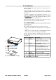
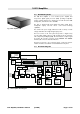
3. D12 Amplifier 3.1. D12 based systems The d&b D12 amplifier is a two channel power amplifier that incorporates digital signal processors (DSP) providing loudspeaker specific controller functions. It is designed for use with all current d&b loudspeakers, and a linear mode is available. The D12 is designed with both digital and analog signal inputs, loudspeaker outputs, and has remote control and monitoring capabilities. Fig.
3.3. Digital signal processing The digital signal processing provides loudspeaker specific setups that are selected using the front panel controls. These setups include all loudspeaker equalization and protection functions. A 4-band parametric equalizer is incorporated in each channel to provide optional Boost/Cut or Notch filtering. A signal delay capability also allows delay settings of up to 340 msec. (= 100 m/328.1 ft) to be applied independently to either channel.
3.4. D12 power amplifiers The two power amplifiers fitted to the D12 can deliver 2 x 750 W continuous sine wave power into an 8 ohms load, increasing to 2 x 1200 W continuous sine wave power into a 4 ohms load. These maximum output ratings measured with sine wave are valid for minutes only until the unit will switch into thermal protect. IMPORTANT! The D12 is specifically designed to produce high power into low impedance loads, typically those between 4 and 16 ohms.
3.6. Power supply The D12 utilizes an autosensing switch mode power supply for mains voltages 115/230 V, 50 – 60 Hz (Optional 100/200 V) and overvoltage protection. Where voltages outside of this range are present, a self-resetting protective circuit responds quickly to isolate the internal amplifier power supply leaving only a supervisory circuit to monitor the mains voltage. The display will clearly indicate the fault and voltage value. The supervision circuit is self-resetting.
3.6.1. Inrush current limiter A mains inrush current limiter provides a "soft start" and enables several D12s to be powered up at the same time without overloading the mains power supply. The maximum current drawn during the power up phase is dependent on the mains voltage, however nominal values are 5 A at 230 V and 10 A at 115 V and 100 V. 3.7. Fan A level and temperature controlled fan is incorporated for cooling the internal components, which allows greater cooling during louder program material.
4. Controls and indicators D12 ISP GR OVL ISP A MUTE GR OVL B OFF ON LEVEL PUSH MENU [4] [3] POWER [2][5][6][7] [1] Fig. 4: D12 Controls and indicators 4.1. Controls 4.1.1. Mains power switch [1] The on/off rotary switch is located on the right hand side at the bottom of the front panel. - OFF: the D12 is isolated from the mains power supply except the overvoltage protection circuit. The power consumption is very low (2 W typical). OFF ON - ON: the D12 is switched on.
- Regular short flashes (1:8 duty cycle): ⇒ STANDBY: in standby mode the loudspeaker outputs are electronically isolated and the D12 idles, drawing minimal mains power. Only the most essential functions are provided. Display and network remain functional, the display illumination is switched off after 10 seconds. Pressing the MUTE A or B switch powers on the D12 ready for use. The D12 may also be powered back on by remote control from standby mode.
4.2. Indicators 4.2.1. LC Display [4] Serves as a user interface and display for all configuration settings and status information. The display is illuminated and can be set to "on/off/timeout 10 s." ISP GR OVL [5][6][7] CH A ISP [4] GR OVL [5][6][7] CH B Fig. 7: D12 Indicators in detail A detailed description of the menu structure and access is given in the D12 Software manual, which is also provided with the D12. 4.2.2.
5. Connections Mains panel I/O panel OUT A C AU TION LINK INPUT R ISK O F ELECT RIC SHOCK DO NOT OPEN RISK OF FIRE - REPLACE FUSE AS MARKED ANALOG CH A FUSE T10A H / 250 V FUSE ANALOG T10A H / 250 V OUT B MAINS SUPPLY REMOTE CH B SERVICE VOLTAGE SEE LABEL ~ 50/60 Hz 1400 W DIGITAL AES/EBU Made in Germany www.dbaudio.com [9a][9b] [8] [10] [11] [15(a/b/c)] [13] [14b] [14a] [12] Fig. 8: D12 Connections 5.1.
5.1.3. REMOTE [10] 1......8 1......8 1. . . . . .8 Pin 1 Pin 2 Pin 3 Pin 4 Pin 5 Pin 6 Pin 7 Pin 8 Shield n.c. n.c. n.c. CAN_H CAN_L n.c. RIB Data + RIB Data CAN Ground Fig. 10: Pin assignment for remote control (RJ 45) The D12 is fitted with a 2-wire serial remote control interface, (2 x RJ 45) carrying both the RIB and CAN-Bus signals. All pins of both connectors are wired in parallel allowing either to be used as the input or output.
5.2. Connector panel (I/O Panel) OUT A LINK All signal input and output connections are located on the rear I/O panel. INPUT ANALOG CH A These include analog and digital (AES/EBU) signal inputs and link outputs for each channel. Loudspeaker outputs are optionally either EP5, NL4 or NL8, dependent on the loudspeaker input version or type. ANALOG CH B OUT B DIGITAL AES/EBU Fig. 12: D12 I/O Panel 5.2.1.
5.2.4.1. Dual channel mode INPUT A AMP A OUT A SenseDrive when SUB selected INPUT B AMP B OUT B SenseDrive when SUB selected Fig. 17: D12 Input/Output routing Dual channel mode with standard input routing In "Dual channel mode" the D12 acts as a two channel amplifier – stereo amplifier. The amplifier channels are connected to their respective output connectors (AMP Ch A to OUT A and AMP Ch B to OUT B).
5.2.5. Loudspeaker wiring The passive full range/TOP systems and passive subwoofers use pins 1 and 2 of the EP5 connector (1+ and 1– of the NL4 connector). Actively driven subwoofers use pins 3/4 and pin 5 of the EP5 connectors (2+ and 2– of the NL4 connector). These pin assignments allow full range cabinets and subwoofers to be linked together and connected to the amplifier in mixed configuration (Mix-TOP/SUB) using a single 4 or 5-wire cable.
6. Installation and operation 6.1. Installation D12 amplifier enclosures are designed to fit a standard 19" equipment rack or cabinet. When specifying a rack, be sure to allow extra depth (10 cm / 4" is usually sufficient) to accommodate the cables and connectors at the rear of the amplifier(s). Fig.
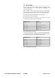
The table gives power figures for various types of signal waveforms. They were measured on a D12 driving a 4 ohm load (both channels) to the clipping point of both channels using a sine wave burst signal of 24 dBu with a variable duty cycle. The mains power supply used for the measurements supplied an ideal sine wave with 230 V/50 – 60 Hz at an internal resistance of 0.5 ohms (0.12/0.1 ohms for 115/100 V) equivalent to a mains lead of 20 m (65.6 ft) with a cross section of 1.
When using the D12 at its upper temperature limit of 45 °C (113 °F), the maximum continuous output power is 500 watts total or 250 watts per channel. Again referring to section 6.2.1 - (Tab. 8) - the unit will work properly with e.g. 400 watts total when either running 4 ohms loads when the signal has a CF of 3.5 or running 8 ohms loads if the worst case signal with a CF of 2.4 needs to be handled.
7. Technical specifications Displays ISP A/B..................................................................Input Signal Present indicator (green) GR A/B.........................................................................Gain Reduction indicator (yellow) OVL A/B...........................................................................Overload/Error indicator (red) MUTE A/B......................................................................
Protection circuits Mains inrush current limiter................................................................5 A RMS at 230 V ......................................................................................................10 A RMS at 115/100 V Speaker switch on delay............................................................................Approx. 2 sec. Overvoltage protection...........................................................................
7.1. Technical drawings LINK OUT A C AU TION D12 INPUT R ISK O F ELECT RIC SHOCK DO NOT OPEN RISK OF FIRE - REPLACE FUSE AS MARKED ANALOG CH A FUSE ISP GR OVL ISP GR T10A H / 250 V OVL FUSE ANALOG T10A H / 250 V A MUTE CH B OUT B B MAINS SUPPLY OFF REMOTE SERVICE VOLTAGE SEE LABEL ~ 50/60 Hz 1400 W ON DIGITAL AES/EBU LEVEL PUSH MENU POWER Made in Germany www.dbaudio.com Fig. 23: D12 front view Fig. 24: D12 rear view GR OVL ISP A MUTE GR 132 [5.
8. Manufacturer's declarations 8.1. EU declaration of conformity (CE symbol) This declaration applies to: - D12, Z2600.000/001 - D12, Z2600.300/301 manufactured by d&b audiotechnik GmbH. All products of type D12 starting from variant Z2600.000 are included, provided they correspond to the original technical version and have not been subject to any later design or electromechanical modifications.
D2012.E.04, 02/2014 © d&b audiotechnik GmbH d&b audiotechnik GmbH, Eugen-Adolff-Str.