D12 Amplifier Software manual (5.5 EN) (Firmware V2.x.
General Information D12 Amplifier Software manual (Firmware V2.x.x) Version 5.5 EN, 02/2013, D2013.E.05 Copyright © 2013 by d&b audiotechnik GmbH; all rights reserved. Keep this manual with the product or in a safe place so that it is available for future reference. When reselling this product, hand over this manual to the new customer. If you supply d&b products, please draw the attention of your customers to this manual. Enclose the relevant manuals with the systems.
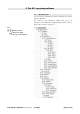
Contents 1. Introduction......................................................................5 1.1 Block diagram of the D12 DSP software............................................5 2. The D12 operating software...........................................6 2.1 D12 menu tree............................................................................................6 2.2 D12 user interface.....................................................................................7 2.2.
3. D12 Firmware update...................................................34 3.1 Firmware Installer....................................................................................34 3.2 D12 Firmware update via D6-D12-dbUpdate...............................34 3.3 D12 Firmware update via CAN-Bus and R10................................34 4. Remote control & monitoring.......................................35 4.1 Remote-Mode "dbCAN".......................................................................35 4.
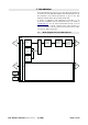
1. Introduction This manual describes the structure, access (user interface) and functions of the firmware of the d&b D12 Amplifier. A detailed description of the D12 hardware and technical specifications is given in the D12 Hardware manual, which is also provided with the D12. A number of publications with supplementary information on our products are available from the documentation section of our website at www.dbaudio.com.
2. The D12 operating software 2.1 D12 menu tree The menu structure of Channel A is shown in detail. The same structure applies to Channel B. The settings for the configuration switches Filter_1/_2/_3 are dependent on the loudspeaker configuration (please refer to section ⇒ Filter_1, Filter_2, Filter_3 on page 11). Key: : Further sub menu : Direct access within the resp. level of hierarchy D12 Software manual (Firmware V2.x.x) (5.
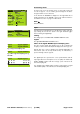
2.2 D12 Stage right L P Q-SUB Q7 -3.0dB +0.0dB CUT HFA ISP EQ 0.1 CSA 100 GR OVL ISP A MUTE D12 L P D EQ GR OVL B D12 user interface The LCD [4] acts as a user interface for all menus within the D12. The cursor is controlled via the digital rotary encoder, LEVEL/PUSH MENU [3]. In the main menu the encoder acts as a level control. Pressing or turning the encoder gives access to different menu levels or allows configurations or values to be entered.
2.3 D12 D12 Boot screen The boot procedure takes approximately 4 seconds during which the device name, the manufacturer's name (d&b audiotechnik) and the firmware version are displayed. d&b audiotechnik D12 V 2.xx The transition to the Main screen is carried out automatically. Fig. 1: D12 Boot screen 2.4 D12 Stage right Q7 Q-SUB -3.0dB +0.0dB CUT HFA EQ 0.01 CSA 100 D12 Main screen The main screen displays all important settings and status information in one view.
D12 Settings menu Settings Back Input Ch A Ch B Link A B Remote Lock Options Id0.01 From the main screen the "Settings menu" is entered by pressing the encoder for approx. 1 sec. It contains general settings for the device and gives further access to submenus. analog Dual channel Q7 Q-SUB off off Press 2s In the first line the dbCAN-ID is displayed on the right hand side. A detailed description of the CAN-ID is given in the submenu "Remote" and the Remote section on page 21 in this manual.
Output (Output routing) Settings Back Input Output Id0.01 analog Dual channel Selecting "Output" and pushing the encoder allows the setting of the following output configurations 1. Dual channel 2. Mix Top/Sub 3. 2-Way Active Depending on the selection the corresponding pin assignment of the loudspeaker output connectors will be set automatically. Note: After a change of the output configuration the D12 outputs are muted. Use the respective MUTE A or MUTE B switches to unmute it.
On the right hand side the software version of the selected speaker configuration is displayed. A change of the loudspeaker type has to be confirmed. This can be done by selecting "Ok" or "+Clear". Both are marked by a flashing question mark (?). Ok Selecting "Ok" and pushing the encoder confirms the configuration and exits the submenu "Speaker Selection".
Equalizer Equalizer off A 4-band parametric equalizer providing optional Boost/Cut (“PEQ”) or Notch filtering is available for each channel independently in the signal path before the limiting circuit. The EQ function has a Master on/off while each of the four bands can be switched independently. In Dual channel or Mix Top/Sub mode the EQ sections of both channels can be linked using the "Link A»B" function in the "Settings menu".
Notch function F Q G The following parameters can be edited: 3 Notch A 3460 Hz 25.00 BW 0.04oct ------- F Filter center frequency adjustable from 20 Hz to 20 kHz in 3 % steps. Q The Q of the filter is adjustable from 0.5 ... 25 in 10 % steps. In addition, the bandwidth (BW) as a result of the Q is displayed as a value (2.0 ... 0.04 octaves) in a non-editable field. G The parameter "Gain" (G) cannot be edited in "Notch" mode. The center frequency is fully attenuated (⇒ –∞ dB). Delay Delay off 0.
Impedance Z The impedance of the loudspeaker(s) presented to the output of the D12, displayed only as a numeric value in ohms. The value is measured with the actual output signal and may therefore vary with its spectral content. The measurement range reaches from 0 ohms (short circuit) to 255 ohms (open loop, I = 0, Z ⇒ ∞). When the signal is too low the maximum of 255 ohms is displayed.
System Check System Check is a powerful and convenient tool to check the condition of either a single d&b loudspeaker or a complete d&b sound system driven by the D12. It is preferably used in conjunction with the d&b Remote network and the R1 software. System Check uses the amplifier's capability to measure the impedance connected to its outputs using a sine wave signal created by the DSP section of its controller. System Check is related to the Load Monitoring feature of the D12.
Calib. Load Monitoring Pilot Signal LF + 0.0dBu Cancel A Calib. Load Monitoring Finished LF 9.1 HF 16.0 Ok A Chk Cal After a successful calibration the reference value is displayed and "Ok" appears in the bottom line of the calibration screen. 0.0 ----- 0.0 0.0 ----- 0.0 LF MF Selecting "Calibrate" starts the calibration procedure while the progress of the procedure is displayed. It can be canceled/interrupted and restarted at any time by pushing the encoder during the procedure.
Load Monitoring menu Load Monitoring A Back Mode off Detection Time 99s Mode Selecting "Mode" within the "Load Monitoring menu" and pushing the encoder (Mode on – indicated as "L " in the main menu) activates "Load Monitoring". D12 Stage right L Q7 Q-SUB -3.0dB +0.0dB Detection Time The maximum time in which a loudspeaker malfunction will be detected by the system. The interval of the pilot signals is derived from this parameter. CUT HFA L D EQ 0.
Calibrate NOTICE: Ensure that all components of the system are wired and working correctly before executing the calibration! Selecting "Calibrate Now" enters the submenu "Calib. Load Monitoring" and the following message will be given as a precautionary measure: Calib. Load Monitoring A Calibration interrupts your audio program! Cancel Calibrate Calib. Load Monitoring Pilot Signal LF + 0.0dBu Cancel A Calib. Load Monitoring Finished LF 9.1 HF 16.
Level Level of the frequency generator in dBu covering a 63.5 dB range from –57.5 dB to +6 dB in 0.5 dB steps. The level value corresponds to the level at the controller signal input. The actual output voltage depends on the channel input gain, the frequency dependent gain of the selected loudspeaker configuration and EQ settings if used. Frequency Frequency adjustable in the range of 1 Hz to 20 kHz in 1 Hz steps.
AmpPreset D12 amplifiers from firmware version V2.12 provide AmpPresets which contain all important user settings of the entire device such as input, output and channel configurations, EQ and delay settings. Using the D12 AmpPresets a sound system can be operated in different configurations (e.g. "Conference", "Music" or "Emergency Call") without the need of transmitting all detailed settings of the devices used.
Name of Preset (empty) Ok Name of Preset MyPreset Preset Name Enables the assignment or editing of a Preset Name (maximum 15 characters): 1. Selecting the "Preset Name field" enters the submenu and the cursor is positioned at the beginning of the field. 2. Pressing the encoder enters edit mode. The pointer, ( ), indicates the entry position for new or edited characters. A variety of characters (e.g. capital and lower case letters, numbers 0-9 and special characters) is displayed in the bottom line. 3.
Sub net 0 to 7 dbCAN Id 0. 01 dbCAN Id 7. 01 dbCAN Id 7. 01 dbCAN Id 7. 63 RIB/RS232: remote control via RS232 and the SERVICE connector of the D12. (indicated as "RIB 2 " in the main screen) dbCAN: remote control via dbCAN (CAN-Bus)/ROPE C. In 2-Way Active mode indicated as "CAN " and the "dbCAN Id", e.g. 7.63 in the main screen. In Dual channel or Mix Top/Sub mode indicated by the "dbCAN Id", e.g. 7.63 in the main screen. dbCAN Id Setting the "dbCAN identifiers [n].[nn]".
1. Selecting "Password" enters the "Edit Password" mode and the cursor is positioned at the beginning of the "Password". 2. Pressing the encoder enters edit mode. The pointer ( ) indicates the entry position for new or edited characters. The selection of characters (Capital letters) is displayed in the bottom line. 3. Each character can be highlighted by turning the encoder. Turning left moves the cursor to the start of the list (A ⇐), turning right to the end of the list (⇒ Z). 4.
Options Options Options Back Device Name Display The "Options" menu allows further settings and status retrieval in addition to the operational configurations and parameters of the device. Device Name D12 X2.0.xx Enables the assignment or editing of a device name (maximum 15 characters): 7. Selecting "Device Name" enters the submenu and the cursor is positioned at the beginning of the "Device Name". As a factory preset "D12" followed by the firmware version is entered. 8.
Information Information Information Back Temp.Amp. 35°C 38°C Temp.PS. 36°C Hardware t.vvv cn Firmware D12 Xn.n.nn DSP-Ver Xn.nn Xn.nn S/N Z2600nnnnnnnn Log Selecting "Information" and pushing the encoder enters the submenu. Temp. Amp. The temperature of the D12 heat sink. Temp. PS The temperature of the D12 Power Supply. Hardware Hardware type and variant [t.vvv] and identification [cn]. Firmware The software version installed in the D12. DSP-Ver The version of active software installed in the D12 DSPs.
SysErr A numerical value indicating the number of times the D12 has entered the error condition "SysErr". RemoteErr A numerical value indicating the number of times the D12 has entered the error condition "RemoteErr". DSP Halt A numerical value indicating the number of times the D12 has entered the error condition "DSP Halt" due to an internal fault. PS Log PS Log Selecting "PS Log" and pressing the encoder enters the submenu. Log Power Supply Back PS Err 1x Overvolt. 0x Temp Off 0x <40°C ...
ImpErrLf A numerical value indicating the number of times the D12 has entered the error condition "ImpErrLf" due to a Load Monitoring fault. ImpErrHf A numerical value indicating the number of times the D12 has entered the error condition "ImpErrHf" due to a Load Monitoring fault. InpMonErr A numerical value indicating the number of times the D12 has entered the error condition "InpMonErr" due to an Input Monitoring fault, possibly caused by a missing external pilot signal. T/S Mis.
Input Monitoring According to the European Standard EN 60849 "Elektroakustische Notfallwarnsysteme" (equivalent to international standard IEC 60849 "Sound Systems for Emergency Purposes") the complete signal chain needs to be monitored. Therefore the "d&b Input Monitoring" functionality allows the detection of an incoming pilot signal to be inserted into the signal chain in front. Important notes on Input Monitoring Input Monitoring can supervise the D12 analog or digital inputs.
Input Monitoring menu Input CheckMonitoring Ok Mode Analog Pilot Input A off Input B off Input Monitoring Input A Back Mode on ... D12 Stage right P Q-SUB Q7 -3.0dB +0.0dB CUT HFA EQ 0.01 CSA 100 Detection Time 1s Detection Time 99s P D EQ 99s on D12 Stage right J12 Active L P n D -3.0dB 0.
Power Supply Power Supply Selecting "Power Supply" and pressing the encoder enters the submenu. Power Supply Back Mains 230V Frequency 50Hz Mains The currently measured mains voltage to which the device is connected in volts. The typical accuracy is 2 %. Frequency The detected mains frequency. Buzzer Buzzer off An additional acoustical signal for error messages. on/off Turning the buzzer on or off.
2.5 Display messages 2.5.1 Error messages Error messages can be related either to the device ("Device") or to a single or both channels of the device ("Channel"). Channel related error messages are supplemented by the channel information. Device System Error [nnn]: an internal fault has occurred. Switch the device off and on again (reboot). The number [nnn] can provide your d&b service partner with information on the cause of the fault.
Channel Amp. Temp. Warn. ([xx] °C): the temperature of the heat sink is very high, the air flow should be checked (fan filter) or the load should be reduced. Channel Amp. Overtemp. ([xx] °C): the temperature of the heat sink is too high and the device is muted and the loudspeaker output is switched off. After cooling down to a permitted operating temperature the device will switch on automatically. Channel Amp. Temp Err. ([xx] °C): the temperature of the heat sink of the device is too high.
2.5.4 Further messages The following messages are intended for information on the status of the D12. They are no error messages. Standby: indicates that the device is in standby mode. Unlock: Press knob 2s: indicates that the device has been locked to protect it against accidental or unauthorized operation. Press and hold the encoder for a minimum of 2 seconds until "Lock" disappears from the lower status line of the LCD. 2.
3. D12 Firmware update Note: A firmware update erases all user settings of the device. The device name and the log files are kept. The operating software – firmware – can be updated in two different ways. 1. Firmware update of a single amplifier via serial interface using the dbUpdate software program. 2. Firmware update of multiple amplifiers via the d&b Remote network (CAN-Bus) using the R10 Service software. In addition, the d&b Firmware Installer is required.
4. Remote control & monitoring 1......8 1......8 1. . . . . .8 Pin 1 Pin 2 Pin 3 Pin 4 Pin 5 Pin 6 Pin 7 Pin 8 Shield n.c. n.c. n.c. CAN_H CAN_L n.c. RIB Data + RIB Data CAN Ground Fig. 11: Pin assignment for remote control (RJ45) The D12 is fitted with a two-wire serial remote control interface, (2 x RJ 45) carrying both the RIB and CAN-Bus signals. All pins of both connectors are wired in parallel allowing either to be used as the input or output.
D2013.E.05, 02/2013 © d&b audiotechnik GmbH d&b audiotechnik GmbH, Eugen-Adolff-Str.