D6 Amplifier Hardware manual (1.
Symbols on the equipment Please refer to the information in the operating manual. WARNING! Dangerous voltage! General Information D6 Amplifier Hardware manual Version 1.9 EN, 02/2014, D2017.EN.01 Copyright © 2014 by d&b audiotechnik GmbH; all rights reserved. Keep this manual with the product or in a safe place so that it is available for future reference. When reselling this product, hand over this manual to the new customer.
Contents 1. Introduction......................................................................4 1.1. Intended use...............................................................................................4 1.2. Scope of supply.........................................................................................4 1.3. Maintenance/Service...............................................................................5 2. D6 Amplifier.....................................................................
1. Introduction This manual describes the facilities and basic functions of the hardware of the D6 amplifier. A detailed description of the D6 software (firmware) menu structure and access is given in the D6 Software manual, which is also provided with the D6. 1.1. Intended use The D6 amplifier is a two channel power amplifier and controller unit. It is designed for use with all current d&b loudspeakers except 2-Way Active, V-Series and B2-SUB systems.
1.3. Maintenance/Service Do not open the unit. No user serviceable parts inside. In case of any damage do not operate the unit under any circumstances. Refer servicing only to qualified service personnel authorized by d&b audiotechnik. In particular if: - objects or liquids have entered the unit. - the unit is not operating normally. - the unit was dropped or the housing is damaged. CAUTION! Potential risk of explosion.
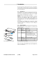
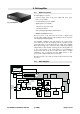
2. D6 Amplifier 2.1. D6 based systems The D6 Amplifier incorporates: - universal voltage, switch mode power supply with active power factor correction (PFC) - two channel Class D power amplifier Fig.
2.3. Power supply The switch mode mains power supply permits worldwide application without the need for mains voltage switching or conversion. The power supply incorporates active Power Factor Correction (PFC) which provides a clean and highly efficient sinusoidal current draw, thus providing highest performance under adverse mains conditions or when very long power cabling is necessary. 2.3.1.
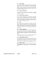
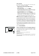
3. Controls and indicators 3.1. Controls 3.1.1. Power switch The power switch [1] is a rocker switch type. It does not isolate the unit from the mains power. - OFF The unit is switched off. The power consumption is low (1 W typical). - ON The unit is switched on and ready for operation. 3.1.2. MUTE A/B switch When the mains power switch is set to the on position, the MUTE A/B switches (push buttons) [2] can be used to mute the respective amplifier channel or place the D6 in Standby mode.
Status indication The switch incorporates a green LED indicator which indicates three different states – ON, MUTE and STANDBY. - LED illuminates permanently ⇒ ON (unmuted) The D6 is ready for use. - LED regular flashing (1:1 duty cycle): ⇒ MUTE The corresponding channel of the D6 is muted however the power amplifiers remain powered but receive no signal from the controller. A connected loudspeaker is therefore still damped.
3.2. Indicators 3.2.1. LC Display The LC Display [4] serves as a user interface and display for all configuration settings and status information. The display is illuminated and can be set to "on/off/timeout 10 s." A detailed description of the menu structure and access is given in the D6 Software manual, which is also provided with the D6. 3.2.2.
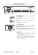
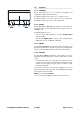
4. Connections D6 CH A MAINS SUPPLY VOLTAGE SEE LABEL ~ 50/60 Hz, 1000 W DIGITAL AES/EBU OUT OUT A REMOTE B 4.1. SERVICE ANALOG CH B Mains connector WARNING! Potential risk of electric shock. The D6 is a protective class 1 unit. A missing earth (ground) contact may lead to dangerous voltages in the housing and controls, and may lead to electric shock. - Connect the unit to mains voltage supplies with protective earth only.
4.2. Signal inputs and link outputs NOTICE: To meet the EMC requirements only use shielded cabling and properly fitted connectors. 4.2.1. INPUT A/B and LINK A/B A 3 pin female XLR input connector [9] is provided for channel A and B. The inputs are electronically balanced. Wired in parallel is a 3 pin male XLR input link connector [10] used to feed the input signal on to the next device in the system signal chain. Fig. 3: Pin assignment ANALOG INPUT/LINK 4.2.2.
4.3. Loudspeaker output connectors - OUT A/B WARNING! Potential risk of electric shock. The amplifier's output pins can carry dangerous voltages. - Only use isolated loudspeaker cables with correctly fitted connectors. - Never connect an amplifier output pin to any other input or output connector pin or protective earth (ground). INPUT A INPUT B AMP A AMP B OUT A OUT B The D6 amplifier is supplied with NL4 output connectors [13]. Pins 1+/2+ and 1—/2— are wired in parallel and carry signal.
4.4. REMOTE interface The D6 is fitted with a 2-wire serial remote control interface, (2 x RJ 45 [14]) carrying CAN-Bus signals. All pins of both connectors are wired in parallel allowing either to be used as the input or output. Where remote control networking conforms to a "Bus or Ring topology" one connector is used for the incoming signal and the second connector allows for direct connection to another device (daisy chaining) or for terminating the last device at the end of a CAN-Bus segment.
5. Installation and operation NOTICE: Observe the operating conditions and limits as given in the technical specifications. Please ensure that ... - no moisture or liquids can enter the unit, e.g. rain, excessive humidity or steam, oil steam or splashes or knocked over liquids (e.g. Drinks). - the unit is not exposed to additional heat, e.g. excessive heat from additional equipment or direct sunlight - no dust or other small particles can enter the unit.
5.2. Operation 5.2.1. Power consumption and power loss The power required from the mains supply and the waste heat produced by the amplifiers power loss vary depending on the load impedance and the signal levels and characteristics (e.g. speech, music). In practice, the theoretical peak power consumption of a system will only be sustained for a short period of time.
5.2.2. Mains supply The table below indicates the number of devices per phase conductor when full output power is required. Mains supply Number of devices 230 V / 16 A Max. 4 115/100 V / 15 A Max. 2 In the USA and Japan we recommend the use of mains leads with a high cross section (min. 4 mm2 / AWG 12). 5.2.3. Operating conditions The following diagram shows the thermal operating range within which the technical data will be maintained.
6. Technical specifications Displays ISP A/B..................................................................Input Signal Present indicator (green) GR A/B.........................................................................Gain Reduction indicator (yellow) OVL A/B...........................................................................Overload/Error indicator (red) MUTE A/B......................................................................
OUT A/B...........................................................................................................................NL4 .....................................................................................Pin assignment: 1+/2+: Output + .....................................................................................................................1–/2–: Output – REMOTE...................................................................................................
Operating conditions Temperature range*...................................................0° C to 40° C / 32° F to 104° F .............................................*sum of average output power of 2 x 200 W (400 W) ................................................................................into 4 ohms for continuous operation Temperature range**.................................................0° C to 45° C / 32° F to 113° F ..........................................................
7. Manufacturer's declarations 7.1. EU declaration of conformity (CE symbol) This declaration applies to - D6 Amplifier, Z2700 manufactured by d&b audiotechnik GmbH. All products of type D6 starting from variant Z2700.000 are included, provided they correspond to the original technical version and have not been subject to any later design or electromechanical modifications.
D6 Amplifier, Hardware manual (1.
D6 Amplifier, Hardware manual (1.
D2017.EN.01, 02/2014 © d&b audiotechnik GmbH d&b audiotechnik GmbH, Eugen-Adolff-Str.