D6 Amplifier Software manual (1.3 EN) (Firmware V1.x.
General Information D6 Amplifier Software manual (Firmware V1.x.x) Version 1.3 EN, 01/2013, D2018.EN .01 Copyright © 2013 by d&b audiotechnik GmbH; all rights reserved. Keep this manual with the product or in a safe place so that it is available for future reference. When reselling this product, hand over this manual to the new customer. If you supply d&b products, please draw the attention of your customers to this manual. Enclose the relevant manuals with the systems.
Contents 1. Introduction......................................................................4 1.1 Block diagram of the DSP software......................................................4 2. The D6 operating software.............................................5 2.1 Menu tree.....................................................................................................5 2.2 User interface..............................................................................................6 2.2.
1. Introduction This manual describes the structure, access (user interface) and functions of the firmware of the d&b D6 amplifier. A detailed description of the D6 hardware and technical specifications is given in the D6 Hardware manual, which is also provided with the D6. A number of publications with supplementary information on our products are available from the documentation section of our website at www.dbaudio.com.
2. The D6 operating software 2.1 Menu tree The menu structure of Channel A is shown in detail. The same structure applies to Channel B. The settings for the configuration switches Filter_1/_2/_3 are dependent on the loudspeaker configuration (please refer to section ⇒ Filter_1, Filter_2, Filter_3 on page 10). Key: : Further sub menu : Direct access within the resp. level of hierarchy D6 Software manual (Firmware V1.x.x) (1.
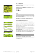
2.2 D6 Stage right Q-SUB CUT HFA EQ EQ User interface The LCD [4] acts as a user interface for all of the menus within the D6. The cursor is controlled via the digital rotary encoder, LEVEL/PUSH MENU [3]. In the main menu the encoder acts as a level control. Pushing or turning the encoder gives access to different menu levels or allows configurations or values to be entered. Also refer to the D6 Hardware manual, section 3. Controls and indicators. 2.2.
2.3 D6 Boot screen The boot procedure takes approximately 4 seconds during which the device name, the manufacturer's name (d&b audiotechnik) and the firmware version are displayed. d&b audiotechnik D6 V X.xx The transition to the Main screen is carried out automatically. Fig. 1: Boot screen 2.4 The main screen displays all important settings and status information in one view. D6 Stage right Q7 Q-SUB -3.0dB +0.0dB CUT HFA EQ 0.
2.5 Settings Back Input Ch A Ch B Remote Lock Options Id0.01 analog Q7 Q-SUB off off Press 2s Settings menu The Settings menu contains general settings for the device and gives further access to submenus. In the first line the dbCAN-Id is displayed on the right hand side. A detailed description of the dbCAN-Id is given in the Remote section on page 20 in this manual. Back Exits the submenu. Fig.
Setup Channel Back Source Input A Speaker Q7 Source Ch A Ch B A Source (Input routing) Input A+B A A B Setup Channel A (B) Q7 Q-SUB Within the submenus "Channel A" and "Channel B" the input source for the respective channel can be selected. Selecting "Source" and pushing the encoder allows the setting of the following routings: Input A The respective channel is fed from input A. Input B Input A+B The respective channel is fed from input B. The respective channel is fed from input A+B.
Speaker CUT HFA CPL Filter_1, Filter_2, Filter_3 Q7 on on off The name of the filter is displayed on the left of the LCD followed by its status or value and a pictogram or graphic representation of the filter's frequency response. The type of filters available depends on the selected loudspeaker configuration. The display [---] indicates that the respective filter is not available for the loudspeaker type selected. on/off The schematic change in response is indicated by the pictogram.
Equalizer Set on Set Selecting "Set" enters the submenu and gives access to the four EQ bands. Turning the encoder to right and pushing the encoder gives access to the individual EQ bands. on 1- 2- 3- 4- A Fig. 7: Equalizer, Set menu F Q G on 1- 2- 3- 4- A on 1- 2- 3- 4- A 1 off 26 Hz 0.99 -18.0dB A BW 1.01oct on 1P 2- 3N 4P A on/off In the submenu "Set" the master switch for the EQ function is also accessible.
Levels Levels Ch A Input Headr. Power -3.0dB Ch B Input Headr. Power +0.0dB : : : Input Headr. Power : : : 36°C -80dBu Z 255 0W Selecting "Levels" and pushing the encoder enters the submenu. 36°C -30dBu Z 7 30W In the "Levels screen" the following values are displayed as bar graphs and/or as numeric values: Turning the encoder one detent to the right and back toggles between channel A and B. Pushing the encoder exits the submenu.
Channel Name Channel Name Channel Name Channel A Enables the assignment or editing of the channel name (maximum 15 characters): Ok 1. Selecting "Channel Name" enters the submenu and the cursor is positioned at the beginning of the "Channel Name". The factory default setting is "Channel" followed by the selected channel (A or B). Cancel Channel Name MyChannel 2. Pressing the encoder enters edit mode. The pointer, ( ), indicates the entry position for new or edited characters.
System Check System Check System Check is a powerful and convenient tool to check the condition of either a single d&b loudspeaker or a complete d&b sound system driven by the D6. It is preferably used in conjunction with the d&b Remote network and the R1 software. System Check uses the amplifier's capability to measure the impedance connected to its outputs using a sine wave signal created by the DSP section of its controller. System Check is related to the Load Monitoring feature of the D6.
Calib. Load Monitoring Pilot Signal LF + 0.0dBu Cancel A Calib. Load Monitoring Finished LF 9.1 HF 16.0 Ok A Chk Cal Confirm to get back to the System Check menu. 0.0 ----- 0.0 0.0 ----- 0.0 LF MF Load Monitoring After a successful calibration the reference value is displayed and "Ok" appears in the bottom line of the calibration screen. HF off If the calibration was not successful (e.g. no load connected), a respective error message will be given out. Also refer to section 2.6.
Load Monitoring menu Load Monitoring A Back Mode off Detection Time 99s Detection Time 1s Detection Time 99s LF Driver HF Driver Calibrate Mode Selecting "Mode" within the "Load Monitoring menu" and pushing the encoder activates "Load Monitoring". The on/off status is indicated as "L " in the Main screen. Detection Time The maximum time in which a loudspeaker malfunction will be detected by the system. The interval of the pilot signals is derived from this parameter.
Calibrate NOTICE: Ensure that all components of the system are wired and working correctly before executing the calibration! Selecting "Calibrate Now" enters the submenu "Calib. Load Monitoring" and the following message will be given as a precautionary measure: Calib. Load Monitoring A Calibration interrupts your audio program! Cancel Calibrate Calib. Load Monitoring Pilot Signal LF + 0.0dBu Cancel A Calib. Load Monitoring Finished LF 9.1 HF 16.
Link A B off Link A»B D6 Stage right L Q7 Q-SUB -3.0dB +0.0dB CUT HFA EQ 0.01 CSA 100 The EQ and/or Delay settings of both channels can be linked using the "Link A»B" function. These functions are then controlled in the Channel A menu, in the Channel B menu the linked functions cannot be edited. L EQ Fig. 9: Link A»B indication on the Main screen On the "Main screen" the "Link A»B" function is indicated by altering the center line to arrows as shown in the graphic opposite.
Preset Last 1 * Back Select 9 Preset Name Recall Store Clear Preset Last 1 * Back Select 9 MyPreset Recall Store Clear Ok? AmpPreset Last 1 * Back Select 9 (empty) - - - - Store Clear Load Save Clear Name of Preset (empty) Ok Name of Preset MyPreset Ok! 9 Cancel 9 jklmnopqrstuvwxyzäöüß01 Select Turning and pushing the encoder provides access to the nine user preset memories to be loaded, saved or cleared.
Remote off Remote Remote BL xxx% Back Mode off dbCAN Id 0. 01 All functions of the D6 can be remotely interrogated via the dbCAN (CAN-Bus). The menu header contains information regarding the actual bus load (BL in %). Fig. 10: Remote menu Mode Selecting "Mode" the following modes for remote control are available: Sub net 0 to 7 dbCAN Id 0. 01 dbCAN Id 7. 01 dbCAN Id 7. 01 dbCAN Id 7. 63 off: no remote control. dbCAN: remote control via dbCAN (CAN-Bus).
Edit Password Enables the input of a new password or editing of an existing password (maximum 7 characters). Factory (default) password DBAUDIO. Edit Password DBAUDIO Ok Cancel Single characters can be kept by simply pressing the encoder and the pointer advances by one space after each entry. Edit Password MASTER The editing position can be scrolled through the characters by pressing and turning the encoder simultaneously. LMNOPQRSTUVWXYZ 1.
Options Back Device Name Display Device Name Device Name D6 Xn.n.nn The editing position can be scrolled through the characters by pressing and turning the encoder simultaneously. Ok Enables the assignment or editing of a device name (maximum 15 characters): Single characters can be kept by simply pressing the encoder and the pointer advances by one space after each entry. 1. Selecting "Device Name" enters the submenu and the cursor is positioned at the beginning of the "Device Name".
Information Information Selecting "Information" and pressing the encoder enters the submenu. Information Back Temp.Amp. 35°C 38°C Temp.PS. 36°C Hardware t.vvv cn Firmware D6 Xn.n.nn DSP-Ver Xn.nn Xn.nn S/N Z2700nnnnnnnn Log Temp. Amp. The temperature of the D6 heat sink for both channel A and channel B. Fig. 13: Information menu DSP-Ver The version of active software installed in the D6 DSPs. Temp. PS The temperature of the D6 Power Supply. Hardware Hardware type and variant [t.
PS Log PS Log Selecting "PS Log" (Power Supply Log) and pressing the encoder enters the submenu. Log Power Supply Back PS Err 1x Overvolt. 0x Temp Off 0x <40°C ... PS Err A numerical value indicating the number of times the D6 has entered the error condition "PS Err". Overvolt. A numerical value indicating the number of times the D6 has entered the error condition "Overvoltage".
InpMonErr A numerical value indicating the number of times the D6 has entered the error condition "InpMonErr" due to an Input Monitoring fault, possibly caused by a missing external pilot signal. DSP Halt A numerical value indicating the number of times the D6 has entered the error condition "DSP Halt" due to an internal fault. Temp. (Temperature Log) Proportionate temperature ranges. They display the proportion of "On Time" the D6 has been operated within the temperature ranges listed.
MUTE A/B Note: Input CheckMonitoring Ok Mode Analog Pilot Input A off Input B off As the MUTE A/B switches isolate the D6 digital controller from the power amplifiers the MUTE A/B switches do not affect the input connectors of the D6 and therefore "Input Monitoring" remains working (also refer to the D6 Hardware manual in section "Controls and indicators – MUTE A/B").
Power Supply Power Supply Selecting "Power Supply" and pressing the encoder enters the submenu. Power Supply Back Mains 230V Frequency 50Hz Buzzer Mains The currently measured mains voltage to which the device is connected in volts. The typical accuracy is 2 %. Frequency The detected mains frequency. off Buzzer An additional acoustical signal for error messages. on/off Turning the buzzer on or off. D6 Software manual (Firmware V1.x.x) (1.
2.6 Display messages 2.6.1 Error messages Error messages can be related either to the device ("Device") or to a single or both channels of the device ("Channel"). Channel related error messages are supplemented by the channel information. Device System Error [nnn]: an internal fault has occurred. Switch the device off and on again (reboot). The number [nnn] can provide your d&b service partner with information on the cause of the fault.
Channel Amp. Overtemp. ([xx] °C): the temperature of the heat sink is too high and the device is muted and the loudspeaker output is switched off. After cooling down to a permitted operating temperature the device will switch on automatically. Channel Amp. Temp Err. ([xx] °C): the temperature of the heat sink of the device is too high. The device is muted and the loudspeaker output is switched off. After cooling down to a permitted operating temperature the device will switch on automatically. 2.6.
2.6.4 Further messages The following messages are intended for information on the status of the D6. They are no error messages. Standby: indicates that the device is in standby mode. Unlock: Press knob 2s: indicates that the device has been locked to protect it against accidental or unauthorized operation. Press and hold the encoder for a minimum of 2 seconds until "Lock" disappears from the lower status line of the LCD. 2.
3. D6 Firmware update Note: A firmware update erases all user settings of the device. The device name and the log files are kept. The operating software – firmware – can be updated in two different ways. 1. Firmware update of a single amplifier via serial interface using the dbUpdate software program. 2. Firmware update of multiple amplifiers via the d&b Remote network (CAN-Bus) using the R10 Service software. In addition, the d&b Firmware Installer is required.
D2018.EN .01, 01/2013 © d&b audiotechnik GmbH d&b audiotechnik GmbH, Eugen-Adolff-Str.