
Specifications


Load Monitoring
A
Back
Mode
off
Detection Time 99s
Detection Time 1s
Detection Time 99s
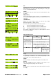
Load Monitoring menu
Mode
Selecting "Mode" within the "Load Monitoring menu" and pushing the
encoder activates "Load Monitoring". The on/off status is indicated as
"
L
" in the Main screen.
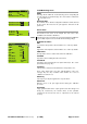
Detection Time
The maximum time in which a loudspeaker malfunction will be detected
by the system. The interval of the pilot signals is derived from this
parameter.
LF Driver
HF Driver
Calibrate Now
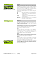
Driver menu
The LF Driver menu serves as an example. The same menu is also
available for the HF and/or MF Driver.
Note:
All settings (except for "Last-Err") are determined during the Calibration
process. Only experienced users should edit the following settings.
Definition of values:
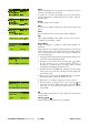
LF Driver
A
Back
Z Min
- 20%
Z Max +30%
Cal 0.0
Last Mon 0.0
Chk 0.0
Last Error 0.0
Pilot Freq 10Hz
Pilot Level -24.5dBu
Threshold 15V
Min
Lower limit of the impedance window which is set to –20 % by default.
Max
Upper limit of the impedance window which is set to +30 % by default.
Calibration
The impedance reference values derived from the calibration.
Last Mon
Impedances detected during the last measurement.
Last Check
Impedances detected during the last System Check (see also section
System Check on page 14).
Last Error
Last impedance values determined that led to an impedance error.
These values will be kept even after acknowledgment of the error
message. They are only overwritten when another error occurs. A
calibration resets them to 0.
Pilot Freq.
Test frequency of the pilot signal for the respective driver.
Pilot Level
Reference level of the pilot signal derived during the calibration
procedure.
Threshold
Large signal threshold. If the output signal exceeds this voltage level
during the measurement, the tolerance limits for this particular
measurement are increased in order to compensate for the reduced
accuracy.
D6 Software manual (Firmware V1.x.x) (1.3 EN) Page 16 of 32