OWNER MANUAL HDL20-A HDL10-A ACTIVE LINE ARRAY MODULES
ENGLISH LANGUAGE ENGLISH 3
ENGLISH SAFETY PRECAUTIONS 1. All the precautions, in particular the safety ones, must be read with special attention, as they provide important information. WARNING: to prevent the risk of fire or electric shock, never expose this product to rain or humidity. WARNING 2. POWER SUPPLY FROM MAINS a. The mains voltage is sufficiently high to involve a risk of electrocution; install and connect this product before plugging it in. b.
ENGLISH 9. Supports and trolleys The equipment should be only used on trolleys or supports, where necessary, that are recommended by the manufacturer. The equipment / support / trolley assembly must be moved with extreme caution. Sudden stops, excessive pushing force and uneven floors may cause the assembly to overturn. 10.
ENGLISH PRODUCT INFORMATIONS The concept of this unique speaker derives from the touring industry, bringing in a compact cabinet all the experience of RCF professional sound. The vocals are natural, the sound is clear at longer distances, the spl power is stable at very high levels. The RCF Precision transducers equipping D LINE have been representing for decades the ultimate performance, the highest power handling and the mos advanced technology in the professional and touring industry.
ENGLISH POWER REQUIREMENTS AND SET-UP The HDL line arrays Systems are designed to operate in hostile and demanding situations. Nevertheless it is important to take extremely care of the AC power supply and set up a proper power distribution. The HDL line arrays Systems are designed to be GROUNDED. Always use a grounded connection.
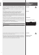
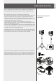
ENGLISH REAR PANEL 6 1 12 7 5 8 4 9 2 3 10 14 13 11 1 MAIN XLR INPUT (BAL/UNBAL). The system accept male XLR/Jack input connectors with line level signals from a mixing console or other signal source. 2 LINK XLR OUTPUT. The output XLR male connector provides a loop trough for speakers daisy chaining. 3 VOLUME. Controls the volume of the power amplifier. The control ranges from (maximum attenuation) to the MAX level ∞ (maximum output). 4 POWER INDICATOR. Power on indicator.
ENGLISH 11 AC POWERCON RECEPTACLE. RCF D LINE uses a POWERCON locking 3-pole AC mains. Always use the specific power cord provided in the package. 12 AC POWERCON LINK RECEPTACLE. Use this receptacle to link one or more units. Always make sure that the maximum current requirement does not exceed the maximum admitted POWERCON current. In case of doubt call the closest RCF SERVICE CENTRE. 13 POWER MAIN SWITCH. The power switch turns the AC power ON and OFF.
ENGLISH SINGLE HDL20-A, HDL10-A The HDL is a flexible system that can be used in ground-supported or suspended applications. The following information will help you set up your HDL system safely and effectively. When using stands or poles, be sure to observe the following precautions: - Check the stand or pole specification to be certain the device is designed to support the weight of the speaker. Observe all safety precautions specified by the manufacturer.
ENGLISH HDL20-A, HDL10-A SUSPENDED - Suspending loads should be done with extreme caution. - When deploying a system always wear protective helmets and footwear. - Never allow people to pass under the system during the installation process. - Never leave the system unattended during the installation process. - Never install the system over areas of public access. - Never attach other loads to the array system. - Never climb the system during or after the installation.
ENGLISH The safety factor is the result of the forces acting on fly bar’s and system’s front and rear links and pins and depends on many variables: - number of cabinets; - fly bar angles; - angles from cabinets to cabinets. If one of the cited variables change the safety factor MUST BE recalculated using the software before rigging the system. In case the fly bar is picked up from 2 motors make sure that the fly bar angle is correct.
ENGLISH 8 Check that all the pins are secured and locked. Rigging the system follow the procedure: RIGGING PROCEDURE H RIGGING CHAIN HOIST. S CERTIFIED SHACKLE. F H FLY BAR. S F 1) Connect the fly-bar F to the chain hoist H (o motors) using the certified shackle. Secure the shackle. 2) Connect the second pin on the front bracket to make sure that the connecting bracket is vertical. A A (2:1) B 3) Connect the front bracket to the first HD cabinet using 2 quick lock pins.
ENGLISH C C (2:1) 4) Reverse and connect the 1 rear bracket to the fly-bar using 2 quick lock pins. The first HDL has to be fixed always starting at 0° with respect of the frame. No other angles are allowded. F 5) Connect the second cabinet to the first always starting from the 2 front brackets. H H (2:1) G G (2:1) 6) Reverse and connect the rear bracket of the second cabinet using the hole for the proper angle.
ENGLISH ARRAY SYSTEMS DESIGN HDL allow users to choose from different face-to-face angle adjustments to create arrays with varying curvature. Thus, designers can create arrays custom-tailored to each venue’s profile. The basic approach to array design dependent on three factors: - Number of Array Elements; - Vertical Splay Angles; - Horizontal Coverage.
COMPUTER REQUIREMENTS Use the RCF Shape Designer for designing HDL arrays. The RCF Shape Designer’s primary function is to determine the configuration that will provide the best vertical performance for a given application. Various venue dimensions are entered that allow the RCF Shape Designer to calculate the resultant array performance. INTRODUCTION Once you have installed RCF Shape Designer, it will be visible as a shortcut in All Programs via your Windows Start button.
ENGLISH ENTERING VENUE DATA For best results, planes should be used as follows: FLOOR is used to simulate the main floor area from the stage to a rear bleacher or boundary. PLANE 1 is used to simulate any audience continuation behind FLOOR (e.g. a rear bleacher) from the end of the main floor to furthest and highest seat below PLANE 2. PLANE 2 is used to simulate the furthest/highest audience area. Enter the height, length and elevation of up to three planes.
SUSPENDED MODE ENGLISH AUTO H SETTING - MIN TRIM HEIGHT This is the low limit for the array and is defined as the smallest allowable distance from the lowest point of the array to the ground below AUTO H SETTING - MAX SUSPENSION POINT Set this to the maximum array height allowable (usually the highest part of the flying frame). The maximum pick height is usually chosen to allow for the maximum flying point height minus a sensible allowance for any shackles, stingers, bridles or flying hooks.
ENGLISH 18 - Cluster Mechanical specifications - Mechanical safety factors MECHANICS PAGE - DSP preset configuration PROCESSOR PAGE - On-axis aiming angle for each enclosure as a difference from 0° horizontal - Various angles and throw distances calculated from the venue’s dimensions - DSP preset configuration - SPL representation on the audience area SPL & REPORT PAGE WARNING: It is possible to display different pages only IN SEQUENCE (venue > array > mechanics > processor > spl & report, and back),
MANUAL MODE ENGLISH RCF Shape Designer works in either of two basic ways: - AUTOMATIC MODE (default setting): The RCF Shape Designer will select the optimum enclosure splays, array aiming angle, fly-bar pick point and DSP preset configurations. - MANUAL MODE: This provides a partial control over the array’s configuration. The enclosure splays can be increased with a progression of 2° steps for each adjacent speaker, in order to maintain a spiral array configuration.
ENGLISH While wave-guides provide isolated control over various mid- to high-frequency coverage areas, the low-frequency section of a HDL array still requires mutual coupling - with equal amplitude and phase - to achieve better directionality. Low-frequency directionality is less dependent on the array’s relative splay angles and more dependent on the number of elements of the array.
ENGLISH 1) Fix the HDL fly bar on subs as shown in the picture. C C (2:1) 2) The stacking bar adds a fixed amount of up or downtilt to ground-stacked HDL loudspeakers, with additional 15 degrees of adjustment possible (from +7,5° to -7,5°). 3) Connect front bracket of the first HDL cabinet using 2 quick lock pins.
ENGLISH 4) The baffle of the bottom box in a stacked array does not necessarily have to be parallel to the stage or the array frame. It can be tilted up or downward if desired. In this way arced arrays can be readily created from a ground stack position. D D (2:1) 5) The bottom box in a stacked array can be tilted to obtain proper coverage patterns (from +7,5° to -7,5°). Reverse and connect the 1 rear stacking bar bracket to the first enclosure using the hole for the proper angle and quick lock pins.
HDL 20-A HDL 10-A 55 Hz - 20 kHz 65 Hz - 20 kHz 135 dB 133 dB 100° 100° 15° max 15° max 2” , 3.0” voice coil 2” , 2.5” voice coil - - 2x10”, 2.5” voice coil 2x8”, 2.
www.rcf.it HEADQUARTERS: RCF S.p.A. Italy tel. +39 0522 274 411 e-mail: info@rcf.it RCF UK tel. 0844 745 1234 Int. +44 870 626 3142 e-mail: info@rcfaudio.co.uk RCF France tel. +33 1 49 01 02 31 e-mail: france@rcf.it RCF Germany tel. +49 2203 925370 e-mail: germany@rcf.it RCF Spain tel. +34 91 817 42 66 e-mail: info@rcfaudio.es RCF USA Inc. tel. +1 732-9026100 e-mail: info@rcf-usa.com 10307302 RevG RCF Benelux tel. +49 (0) 2203 9253724 e-mail: belgium@rcf.