DFE-916x DFE-916 Ethernet/Fast Ethernet Dual-Speed Stackable Hubs User’s Guide Rev. 02 (January, 1998) 6DFE916...
Wichtige Sicherheitshinweise 1. Bitte lesen Sie sich diese Hinweise sorgfältig durch. 2. Heben Sie diese Anleitung für den spätern Gebrauch auf. 3. Vor jedem Reinigen ist das Gerät vom Stromnetz zu trennen. Vervenden Sie keine Flüssig- oder Aerosolreiniger. Am besten dient ein angefeuchtetes Tuch zur Reinigung. 4. Um eine Beschädigung des Gerätes zu vermeiden sollten Sie nur Zubehörteile verwenden, die vom Hersteller zugelassen sind. 5. Das Gerät is vor Feuchtigkeit zu schützen. 6.
Limited Warranty Hardware: D-Link warrants its hardware products to be free from defects in workmanship and materials, under normal use and service, for the following lengths of time from the date of purchase from D-Link or its Authorized Reseller: Product Type Network adapters Unmanaged and managed hubs (10Mbps) Unmanaged hubs (100Mbps) Managed hubs (100Mbps) Warranty Period Lifetime Lifetime * Lifetime * One year Unmanaged and managed dual-speed hubs (10Mbps / 100Mbps) One year Repeaters, MAUs , trans
WARRANTIES EXCLUSIVE IF THE D-LINK PRODUCT DOES NOT OPERATE AS WARRANTED ABOVE, THE CUSTOMER'S SOLE REMEDY SHALL BE, AT D-LINK'S OPTION, REPAIR OR REPLACEMENT. THE FOREGOING WARRANTIES AND REMEDIES ARE EXCLUSIVE AND ARE IN LIEU OF ALL OTHER WARRANTIES, EXPRESSED OR IMPLIED, EITHER IN FACT OR BY OPERATION OF LAW, STATUTORY OR OTHERWISE, INCLUDING WARRANTIES OF MERCHANTABILITY AND FITNESS FOR A PARTICULAR PURPOSE.
Trademarks Copyright 1997 D-Link Corporation. Contents subject to change without prior notice. D-Link is a registered trademark of D-Link Corporation/D-Link Systems, Inc. All other trademarks belong to their respective proprietors. Copyright Statement No part of this publication may be reproduced in any form or by any means or used to make any derivative such as translation, transformation, or adaptation without permission from D-Link Corporation/D-Link Systems Inc.
TABLE OF CONTENTS 0 ABOUT THIS GUIDE .........................................................VIII Conventions........................................................................................viii Overview of the User’s Guide .............................................................viii 1 INTRODUCTION ................................................................. 1 Product Description ..............................................................................1 Product Features..............
Dual-Speed Stackable Hubs User’s Guide 3 UNDERSTANDING INDICATORS ......................................... 15 Hub State Indicators............................................................................16 Module Indicators (SLOT) ...................................................................17 Port State Indicators............................................................................17 Port Speed Indicators ..........................................................................
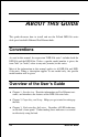
0 ABOUT THIS G UIDE This guide discusses how to install and use the D-Link DFE-916 series dual-speed stackable Ethernet/Fast Ethernet hubs. Conventions As used in this manual, the expression "DFE-916 series" includes both the DFE-916 and the DFE-916x. Unless a specific model number is given, the term "hub" (or "hubs") refers to any unit (or units) in this series. Most of the information in this manual applies to all DFE-916 and DFE916x units.
Dual-Speed Stackable Hubs User’s Guide ♦ Chapter 4, Making Connections. Provides information on connecting to the hub’s twisted-pair and console ports, stacking hubs, and linking with other hubs. ♦ Appendix A, Cables and Connectors. Provides specifications on the cables and connectors used with the hubs. ♦ Appendix B, Specifications. Lists the hubs’ specifications.
Dual-Speed Stackable Hubs User’s Guide 1 1 I NTRODUCTION This chapter introduces DFE-916 series dual-speed stackable hubs, as well as giving some background information about the technology the hubs use. Product Description D-Link DFE-916 series dual-speed stackable Ethernet/Fast Ethernet hubs are designed to allow easy migration and integration between 10Mbps Ethernet and 100Mbps Fast Ethernet, while providing manageability and flexibility in cable connections. Each hub can operate with both IEEE 802.
In the basic configuration, 10Mbps and 100Mbps segments are separate and do not intercommunicate. An optional DFE-260S switching module (included with the DFE-916x) can be installed in any hub in the stack, making it possible to transparently bridge between 10Mbps and 100Mbps segments. In a managed hub stack, more than one DFE-260S module can be used to provide automatic redundancy. Other add-in modules are also available, providing switched 100BASE-TX or switched 100BASE-FX connections.
Dual-Speed Stackable Hubs User’s Guide ♦ A stack can contain various DFE-916 series models and DFE-2624 and DFE-2616 series models. For SNMP management, DFE-916 and DFE-916x units can be managed through a DFE-2616i/DFE2616ix or DFE-2624i/DFE-2624ix master hub. ♦ LED indicators for power, collisions, link, network activity, partitioning status, disable, operating speed (10 or 100Mbps) and network utilization. ♦ Digital hub ID number front panel display. ♦ Auto-partitioning for network protection.
technologies, especially when network hosts are being gradually migrated to new Fast Ethernet connections. A dual-speed hub is actually two repeaters in one enclosure. The 10Mbps repeater receives Ethernet transmissions from any of its ports, and retransmits them to all other ports operating at 10Mbps. Similarly, the 100Mbps repeater retransmits Fast Ethernet transmissions from ports operating at 100Mbps to all other ports operating at the same speed.
Dual-Speed Stackable Hubs User’s Guide 10Mbps Repeater 100Mbps Repeater NWay Detection DFE-260s Switch Module RJ-45 Ports 100Mbps Ethernet Station 100Mbps Ethernet Station 10Mbps Ethernet Station 10Mbps Ethernet Station 100Mbps Ethernet Station 100BASE-TX Technology Overview 100Mbps Fast Ethernet Introduction Computers today have become increasingly powerful, with the capability to accommodate very sophisticated uses such as multimedia applications, video-conferencing, and CAD/CAM.
CSMA/CD Ethernet protocol. Since Fast Ethernet is compatible with all 10Mbps Ethernet environments, it provides a straightforward upgrade without wasting the company’s existing investment in hardware, software, and trained personnel. Cables and Connectors Category 5 unshielded twisted-pair (UTP) cables and shielded twisted-pair (STP) cables are both supported. Category 5 UTP cables use the same RJ45 connector used with 10BASE-T, wired in the same configuration.
Dual-Speed Stackable Hubs User’s Guide Network Diameter Network diameter, which is the distance between two end-stations in the same collision domain, is the primary difference between traditional Ethernet and Fast Ethernet. Due to the increased speed in Fast Ethernet and adherence to the EIA/TIA 568 wiring rules, the network diameter of a Fast Ethernet collision domain is limited to 205 meters; in contrast, the maximum 10BASE-T Ethernet collision domain diameter can be up to 500 meters.
Dual-Speed Stackable Hubs User’s Guide 2 2 UNPACKING AND S ETUP This chapter provides information on the unpacking and initial installation of your hub stack. Unpacking Open the shipping carton of your hub and carefully unpack the contents.
Identifying External Components This section identifies all the major external components of the hub. Both the front and rear panels are shown, followed by a description of each panel feature. The indicator panel is described in detail in the next chapter. Front Panel ♦ LED Indicator Panel Refer to the next chapter, Understanding Indicators, for detailed information about each of the hub’s LED indicators. ♦ Twisted-Pair Ports Use any of these ports to connect stations to the hub.
Dual-Speed Stackable Hubs User’s Guide For more information about crossover connection, see the section entitled Crossover Cables section on page 30. ♦ Uplink Port The Uplink port is an MDI-II port, which means you can connect the hub (or hub stack) to another device with MDI-X ports using an ordinary straight-through cable, making a crossover cable unnecessary. Port 1 and the Uplink port are really the same port, except that their pinouts are different.
hubs can be created in this way. The first and last hubs in the stack use only one of the daisy-chain ports, while the others use both. ♦ Daisy-Chain OUT Port Works in conjunction with the Daisy-Chain IN Port (see above). Connect this port to the Daisy-Chain IN Port of the next hub in the stack (usually placed immediately below it), using the enclosed daisy-chain cable. ♦ Fan Provides air circulation and heat dissipation. ♦ AC Power Connector For the power cord.
Dual-Speed Stackable Hubs User’s Guide ♦ Leave at least 10cm of space at the front and rear of the hub for ventilation. ♦ Install the hub on a sturdy, level surface that can support its weight. When installing the hub stack on a level surface, attach the rubber feet to the bottom of each device. The rubber feet cushion the hub and protect the hub case from scratches. Rack Mounting The hub can be mounted in an EIA standard-size, 19-inch rack, which can be placed in a wiring closet with other equipment.
Connecting the Power Supply Power is supplied to the stackable Fast Ethernet hub through an AC power cord. The AC power input voltage ranges from 100 to 240 VAC. A power cord is included with the device.
Dual-Speed Stackable Hubs User’s Guide 3 3 UNDERSTANDING I NDICATORS Before connecting network devices to the hub, take a few minutes to look over this section and familiarize yourself with the front panel LED indicators of your dual-speed hub, depicted below.
Hub State Indicators ♦ Power Indicator This indicator lights green when the hub is receiving power; otherwise, it is off. ♦ Collision Indicators (COL10M and COL100M) These indicators indicate data collisions on the respective 10Mbps Ethernet or 100Mbps Fast Ethernet segments of the hub. (If several hubs are stacked or linked together, all of them should detect and indicate the same collision, since collisions span the entire network segment.
Dual-Speed Stackable Hubs User’s Guide Module Indicators (SLOT) The module indicator indicates a good link to a module installed in the respective slot. For the DFE-260S switching module, the indicator will come on when the module is installed. For the DFE-260FX and DFE-260TX modules, the slot link indicator should light whenever the module is installed and there is a valid link.
♦ Auto-partition (blinking amber) The indicator of a port blinks amber when the port is automatically partitioned due to an abnormal network condition. The hub will temporarily partition a port when too many line errors or too many collisions are detected on the port. While the segment is automatically partitioned, the port will be isolated from the rest of the network segment. When the problem is corrected or a valid data packet is received through the port, the port is automatically reconnected.
Dual-Speed Stackable Hubs User’s Guide 4 4 MAKING CONNECTIONS This chapter discusses how to make connections to the hub’s twisted-pair ports, cascading hubs to create a stack, and linking with other hubs (or hub stacks). Hub Cascading/Building a Stack You can stack up to five hubs using the daisy-chain ports to form one logical hub. In this configuration, the interconnected hubs constitute a single logical unit, providing a maximum of 80 twisted-pair ports.
Hubs should not be added to the stack or removed from the stack while the power is on to any hub in the stack. Always turn off power to the entire stack before adding or removing hubs. Connectivity Rules Ethernet (10Mbps) networks have the following connectivity rules: ♦ The maximum length of a twisted-pair cable segment is 100 meters. Cabling should be Category 3 or better.
Dual-Speed Stackable Hubs User’s Guide FL), while the remaining segments may be populated (mixing) segments (e.g., 10BASE-2 or 10BASE-5). Fast Ethernet (100Mbps) networks have the following connectivity rules: ♦ The maximum length of a twisted-pair segment (that is, the distance between a port in the hub to a single-address network device such as a PC, server, or Ethernet switch) is 100 meters. Cabling and other wiring should be certified as Category 5 UTP or shielded twistedpair (STP).
When connecting a PC or a server, the system being connected should have an Ethernet or Fast Ethernet network interface card with a twisted-pair port.
Dual-Speed Stackable Hubs User’s Guide Hub-to-Hub Uplink You can link two hubs or hub stacks to each other using any of the twistedpair ports or the Uplink port. Linking hubs using ordinary twisted-pair ports requires crossover twisted-pair cables; linking using one ordinary twisted-pair port and the Uplink port requires an ordinary straight-through twisted-pair cable. The Uplink port is shared with Port 1, and you should not use both Port 1 and the Uplink port at the same time.
A crossover cable is a straight-through twisted-pair cable in which the wires have been crossed. The figure below shows the pin assignments for an Ethernet or Fast Ethernet crossover cable: NOTE: The first twisted-pair port (Port 1) is shared with the Uplink port. If you connect a hub to the Uplink port, then do not use Port 1. Optional Module Connections There are three optional modules that may be added to any of the DFE-916 series hubs. Each hub can accommodate one module.
Dual-Speed Stackable Hubs User’s Guide 1. Locate the module slot in the hub’s rear panel. 2. Using a screwdriver, undo the two screws and remove the dust cover on the module slot. 3. Holding the module component-side up and connector-side in, gently slide the module along the guides and seat it in the internal connector. 4. Using a screwdriver, replace the two screws and tighten until snug.
Fiber Optic Module (DFE-260FX) A fiber optic module provides a standard Fast Ethernet 100BASE-FX fiber optic connector. A fiber optic connection is particularly useful for creating a link between two DFE-916 series hub stacks, placing them in separate collision domains. A link of this sort eliminates the need for a separate switch to separate stacks into separate domains.
Dual-Speed Stackable Hubs User’s Guide Fast Ethernet Module (DFE-260TX) A Fast Ethernet module provides one additional twisted-pair Fast Ethernet connection. A twisted-pair connection of this kind is particularly useful for creating a link between two DFE-916 series hub stacks, placing them in separate collision domains. A link of this sort eliminates the need for a separate switch to separate stacks into separate domains.
• Collision—This LED blinks when there are packet collisions on the module link. • FDX—This LED is lit when the port is set for full duplex transmit and receive. When the LED is off, the port is in half duplex mode. The duplex mode DIP switch allows you to set the port to full duplex mode operation. Only the right-hand switch (number 2) is active. Use the DIP switch to set the duplex mode.
Dual-Speed Stackable Hubs User’s Guide A 5 CABLES AND CONNECTORS 100BASE-TX Ethernet Cable and Connectors ♦ Cable characteristics: Category 5 unshielded twisted-pair or EIA/TIA-568 compliant, 100-ohm shielded twisted-pair data cable with 0.4 to 0.6 mm (22 to 26 AWG) wires in two or four twisted pairs (only two pairs/four wires are used for 100BASE-TX).
Dual-Speed Stackable Hubs User’s Guide Straight Twisted-Pair Cable Pinouts Contact MDI-X Signal MDI-II Signal 1 RD+ (receive) TD+ (transmit) 2 RD- (receive) TD- (transmit) 3 TD+ (transmit) RD+ (receive) 4 Not used Not used 5 Not used Not used 6 TD- (transmit) RD- (receive) 7 Not used Not used 8 Not used Not used Crossover Cables When cascading or connecting the hub to another hub, or to a switch or bridge, through a UTP port, a modified crossover cable is necessary.
Dual-Speed Stackable Hubs User’s Guide 2. At the other end of the cable, connect wires 1 and 2 to contacts 3 and 6, respectively. Likewise, connect wires 3 and 6 to contacts 1 and 2.
Dual-Speed Stackable Hubs User’s Guide B 6 S PECIFICATIONS General Standards: IEEE 802.3 10BASE-T Ethernet repeater, IEEE 802.3u 100BASE-TX Fast Ethernet repeater (Class II); ANSI X3T9.
Hub-to-Hub Cascading Number of Daisy-Chained Hubs: Maximum of 5 hubs per stack Daisy-Chain Port: MiniSCSI-type connector × 2 Daisy-Chain Cable: SCSI-type cable (supplied) LED Indicators Hub Status: Power, 10Mbps collision, 100Mbps collision, 10Mbps utilization, 100Mbps utilization, module link Port Status (per port): Link/Activity/Auto Partition/Manual Disable, Speed (10/100Mbps) Environmental and Physical Power Supply: 100 to 240 VAC, 50 or 60 Hz internal universal power supply Power Consumption: DFE-916
Dual-Speed Stackable Hubs User’s Guide Storage Temperature: -25 to 55°C Humidity: 5% to 95% non-condensing DC Fan: 40mm × 40mm × 10mm Emissions: FCC Class A, CE, VCCI Class A, C-Tick Safety: UL, CSA, CE Mark, TÜV/GS Specifications 35
Offices U.S.A. D-LINK SYSTEMS, INC. 5 Musick Irvine, CA 92618 USA TEL: 1-714-455-1688 FAX: 1-714-455-2521 CANADA D-LINK CANADA, INC. 2180 Dunwin Drive, Unit # 6, Mississauga Ontario, L5L 5M8, Canada TEL: 1-905-828-0260 FAX: 1-905-828-5669 U.K. D-LINK (EUROPE) LTD. D-Link House, 6 Garland Road, Stanmore, London HA7 1DP U.K. TEL: 44-181-2355555 FAX: 44-181-2355500 GERMANY D-LINK (DEUTSCHLAND) GMBH I.G.
Registration Card Print, type or use block letters. Your name: Mr./Ms_____________________________________________________________________________ Organization: ________________________________________________ Dept.