DWL-AG700AP Install Guide User’s Guide Version 3.
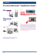
System Requirements Installation ANT24-0700 Install Guide D-Link Antenna-kit Installation Guide Note: /antenna (If needed) Install the surge protector. (You can install with optional ANT24 series low loss cables) With Surge protector adaptor on an outdoor serial is attached to the lightning protestion system (ground) of the building. All devices downstream are then protected by the ground from lightning strikes.
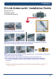
System Requirements Installation D-Link Antenna-kit Installation Guide Surge protector Installation guide for outdoor antenna-kit Step 1 loosen the screw from the surge protector. Option (1) Option (2) Step 2 get a normal conductive copper wire with 2 sides stripped long enough to be conductive, these wires can lead high voltage surges into the grounding.
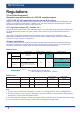
System Requirements ANT24-Series ANT24-0700 Install Guide Regulations D-Link WLAN Antenna-Kit Extended range differentiation for FCC/CE regulated regions CE ETSI EN 300 328 regulated European Union (EU) regions Based on ETSI EN 300 328, the system device and its antenna Emitted Isotropic Radiated Power (EIRP) are limited to operate within a 20dBm gain. The range extension provided by the antenna kit should comply with the restrictions set by the EU. FCC regulated regions (US, Canada, etc.
System Requirements ANT24-Series
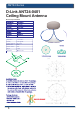
System Requirements ANT24-Series ANT24-0700 Install Guide D-Link ANT24-0401 Ceiling Mount Antenna Electrical specification 58°~75° 110g without joint Environmental & Mechanical Characteristics Temperature -10°C to 55°C Humidity 100% @ 25 C Lightning protection DC ground Radome color white Radome material ABS Weight 100gw Dimensions 132 x 42 mm 120
System Requirements ANT24-Series D-Link ANT24-0500 Indoor/Outdoor Omni-Directional Antenna Omni-Directional Antenna for 2.4 GHz Version 1 Electrical specification SAA04-050170 Electrical Specification Frequency range Ø19×330mm 2400 MHz - 2500 MHz Gain 5.0 dBi VSWR 2.0 : 1 Max.
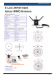
System Requirements ANT24-Series ANT24-0700 Install Guide D-Link ANT24-0501 Indoor Omni-Directional Antenna Electrical specification Frequency Range 2400~2500MHz Impedance 50Ω Normal VSWR 1.92 Max Return Loss -10 dB Maximum Antenna Structure Helis antenna Peak Gain ( w/o cable loss) 5dBi Admitted Power 1W Cable loss( 1.5m) 2.1dB@2.45GHz E-Plane 36 deg. H-Plane 360 deg. ANT24-0700 / ANT24-0700C Far-field amplitude of D-link-7dBi-H1-1020.
System Requirements ANT24-Series D-Link ANT24-0501C Indoor Omni-Directional Antenna Electrical specification Frequency Range 2400~2500MHz Impedance 50Ω Normal VSWR 1.92 Max Peak Gain 5dBi Admitted Power 1W E-Plane 36 deg. H-Plane 360 deg. Physical Properties Connector Reverse SMA plug Antenna Material ABS, ABS+PC Operating Temp -20°C ~ +65°C Storage Temp -30°C ~ +75°C Color Antenna: Metallic gray and silver 36° Attach to AP/Router Package Contents -One ANT24-0501C 2.
System Requirements ANT24-Series ANT24-0700 Install Guide ANT24-Series D-Link D-Link ANT24-0502 ANT24-0502 Indoor Omni-Directional Indoor Omni Directional AntennaAntenna Electrical Specification Frequency range 2400 MHz - 2500 MHz Gain 5.0dBi VSWR 2.
System Requirements ANT24-Series D-Link DWL-50AT Indoor Omni-Directional Antenna Electrical specification 5.0dBi Typical 2.0:1 Max. 360° 30 degree nominal 197 mm(length) 29.5gw 30° Far-field Far-field amplitude amplitude of of C147-510017-A-V.nsi C147-510017-A-V.nsi 2.4GHz 2.4GHz 2.45GHz 2.45GHz 330 330 345 345 0 0 2.5GHz 2.
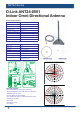
System Requirements ANT24-Series ANT24-0700 Install Guide D-Link ANT24-0600 Indoor Directional Antenna Electrical specification Frequency Range 2400~2500MHz Impedance 50Ω Normal VSWR 1.92 Max Return Loss -10 dB Maximum Antenna Structure Pateh antenna Peak Gain ( w/o cable loss) 6.0 dBi @ 2.45GHz ( typical) Admitted Power 1W Cable loss( 1.5m) 2.1dB@2.
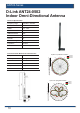
System Requirements ANT24-Series D-Link ANT24-0700 Indoor Omni-Directional Antenna Electrical specification Frequency Range 2400~2500MHz Impedance 50Ω Normal VSWR 1.92 Max Return Loss -10 dB Maximum Antenna Structure Helis antenna Peak Gain ( w/o cable loss) 7dBi Admitted Power 1W Cable loss( 1.5m) 2.1dB@2.45GHz E-Plane 24 deg. H-Plane 360 deg. Physical Properties Cable RG-178 50Ω Cable length 1.
System Requirements ANT24-Series ANT24-0700 Install Guide D-Link ANT24-0700C Indoor Omni-Directional Antenna Electrical specification Frequency Range 2400~2500MHz Impedance 50Ω Normal VSWR 1.92 Max Return Loss 10 dB Maximum Antenna Structure Helis antenna Peak Gain ( w/o cable loss) 7dBi Admitted Power 1W Cable loss( 1.5m) 2.1dB@2.45GHz E-Plane 24 deg. H-Plane 360 deg. Physical Properties Cable RG-178 50Ω Cable length 1.
System Requirements Omni-Directional Antenna for 2.4 ANT24-Series GHz D-Link ANT24-0800 Indoor/Outdoor ANT24-0800A2 Omni-Directional Antenna Electrical specification Electrical Specification Frequency range 2400 MHz - 2500 MHz Gain 8.0 dBi VSWR 2.0. : 1 Max. Polarization Linear, vertical o HPBW / horizontal Ø19×520mm360 340g without joint o HPBW / vertical 15 Environmental & Mechanicalo Characteristics Downtilt 0 Omni-Directional Antenna for 802.
System Requirements ANT24-Series ANT24-0700 Install Guide D-Link ANT24-0801 Indoor/Outdoor Directional Panel Antenna Electrical specification Frequency 2400~2500MHz Gain 8.5 dBi VSWR 1.
System Requirements ANT24-Series D-Link ANT24-1200 Indoor Directional Panel Antenna Electrical specification Frequency range 2400 MHz - 2500 MHz Gain 12 dBi VSWR 1.
System Requirements ANT24-Series ANT24-0700 Install Guide D-Link ANT24-1201 Outdoor Directional Yagi Antenna Electrical specification Frequency range 2400 MHz - 2500 MHz Gain 12 dBi VSWR 1.
System Requirements ANT24-Series D-Link ANT24-1202 Outdoor Omni-Directional Antenna 19
System Requirements ANT24-Series ANT24-0700 Install Guide D-Link ANT24-1400 Outdoor Directional Panel Antenna Electrical specification Frequency range 2400 MHz - 2500 MHz Gain 14 dBi VSWR 1.
System Requirements ANT24-Series D-Link ANT24-1800 Outdoor Directional Panel Antenna Electrical specification Frequency range 2400 MHz - 2500 MHz Gain 18 dBi VSWR 1.
System Requirements ANT24-Series ANT24-0700 Install Guide D-Link ANT24-2100 Outdoor Directional Antenna 22
System Requirements ANT70-Series D-Link ANT70-0800 Dual-Band Omni-Directional Antenna Dual-Band Omni-Directional Antenna Electrical specification forFrequency 2.4 /Range 5.2 / 5.4 GHz 2400 MHz - 2500 MHz Gain 8 dBi VSWR ANT70-0800 4900 MHz - 5470 MHz 8 dBi 2.0 : 1 Max. HPBW / horizontal 360° Polarization Linear, vertical HPBW / vertical 15° Electrical Specification Frequency range 24005 W MHz Power handling (cw) - 2500 MHz 4900 MHz - 5470 MHz GainImpedance 8 dBi50 Ohms VSWR 2.0 : 1 Max.
System Requirements ANT70-Series ANT24-0700 Install Guide D-Link ANT70-0801 Dual-Band Omni-Directional Antenna Dual-Band Omni-Directional Antenna for 2.4 / 5.4 / 5.6 / 5.8 GHz Electrical specification Frequency Range 2400 MHz - 2500 MHz 5400 MHz - 5875 MHz ANT70-0801 Gain 8 dBi VSWR 8 dBi 2.0 : 1 Max.
System Requirements ANT70-Series D-Link ANT70-1000 Dual-Band Directional Panel Antenna Electrical specification Frequency Range 2400 MHz - 2500 MHz 4900 MHz - 5875 MHz Gain 8.5 dBi 10.5 dBi VSWR 2.0 : 1 Max. 2.0 : 1 Max. HPBW / horizontal 58° 45° HPBW / vertical 55° 45° Polarization Linear, vertical Power handling 5 W (cw) Front to back ratio 15dB Downtilt 0° Impedance 50 Ohms Connector N Jack 2.
System Requirements ANT70-Series ANT24-0700 Install Guide D-Link ANT70-1800 Dual-Band Directional Panel Antenna Electrical specification Frequency Range 2400 MHz - 2500 MHz 4900 MHz - 5875 MHz Gain 14 dBi 18 dBi VSWR 2.0 : 1 Max. 2.0 : 1 Max. HPBW / horizontal 30° 15° HPBW / vertical 30° 15° Polarization Linear, vertical Power handling 10 W (cw) Front to back ratio 15dB Downtilt 0° Impedance 50 Ohms Connector N Jack 2.
System Requirements Fresnel Zone Line-of-Sight (LOS) Visual and RF Line-of-Sight ( LOS ) between the sending and receiving antennas is essential in achieving long range in wireless communication systems. There are two types of LOS that are generally used to describe an environment: Visual LOS is the ability to see from one site to the other. It requires only a straight liner path between two points.
System Requirements Fresnel Zone ANT24-0700 Install Guide How far above the ground and other obstacles the antennas need to be is determined by the radius of the Fresnel zone. The radius of the Fresnal Zone depends upon the frequency and distance between the two radios. The following table provides approximate Fresnel zone radius: In order to have LOS clearance, the combined antenna height should be equal to or at least 70% of the radius of the Fresnel zone.
--- Optional antenna cable kits Desktop Default mounting configuration --- --- Default extension cable length Optional accessories --- PR-SMA plug 1.2 m H360 V70 Surge protector for outdoors Antenna fixed connector Pigtail cable length Half Power Beam width --- Approximate Range at 1/ 11 /54Mbps (Works with Outdoor AP) 1.
Wall/ desktop/magnetic Default mounting configuration Optional antenna cable kits --- --- --- Default extension cable length Optional accessories --- RP-SMA plug 150cm Surge protector for outdoors Antenna fixed connector Pigtail cable length H360 V24 --- Approximate Range at 1/ 11 /54Mbps (Works with Outdoor AP) Half Power Beam width 550m/ 250m/60m Approximate Range at 1 / 11/ 54Mbps ( Works with Indoor AP ) 7dBi Indoor only Application range Gain (Without cable loss) Omni-direct
Included 50cm Wall/ pole Surge protector for outdoors Default extension cable length Default mounting configuration Optional antenna cable kits ANT24-CB series --- N-jack Antenna fixed connector Optional accessories 30cm Pigtail cable length H360 V6 3Km / 1.
2.4GHz: 700m/ 350m/ 100m 5GHZ: 1K/ 500m/ 200m 2.4GHz: 800m/ 450m/ 150m 5GHZ: 1K/ 500m/ 200m 2.4GHz: H360 V15 5GHz: H360 V15 2.4GHz: 8dBi 5GHz: 8dBi 2.4GHz: 700m/ 350m/ 100m 5GHZ: 1K/ 500m/ 200m 2.4GHz: 800m/ 450m/ 150m 5GHZ: 1K/ 500m/ 200m 2.
͞΄;Ͳ͑ΝΦΘ Ϳ͑ΝΦΘ RP Ϳ-Jack ͞΅Ϳʹ͑ΝΦΘ Ϳ͑ͻΒΔΜ ͞΄;Ͳ͑ͻΒΔΜ͙͑͵͞ͽΚΟΜ͑Ͳ͑͠ΠΦΥΖΣ͚͑ ͞Ϳ͑ΝΦΘ͑ CONNECTORS OUTLOOK (Appendix) System Requirements 33
Ver. 3.