D-Link™ DES-1250G Web Smart 48-Port 10/100Mbps+2-Port Combo 10/100/1000Mbps Copper/SFP(Mini GBIC) Gigabit Switch Manual Second Edition Building Networks for People RECYCLABLE
Information in this document is subject to change without notice. © 2004 D-Link Computer Corporation. All rights reserved. Reproduction in any manner whatsoever without the written permission of D-Link Computer Corporation is strictly forbidden. Trademarks used in this text: D-Link and the D-LINK logo are trademarks of D-Link Computer Corporation; Microsoft and Windows are registered trademarks of Microsoft Corporation.
CE Mark Warning This is a Class A product. In a domestic environment, this product may cause radio interference in which case the user may be required to take adequate measures. Warnung! Dies ist ein Produkt der Klasse A. Im Wohnbereich kann dieses Produkt Funkstoerungen verursachen. In diesem Fall kann vom Benutzer verlangt werden, angemessene Massnahmen zu ergreifen. Precaución! Este es un producto de Clase A.
About This Guide...................................................................................................................................................................................... 5 Purpose ................................................................................................................................................................................................. 5 Terms/Usage ...............................................................................................
ABOUT THIS GUIDE Congratulations on your purchase of the Web Smart 48+2G-Port 10/100/1000Mbps/SFP Switch. This device integrates 1000Mbps Gigabit Ethernet, 100Mbps Fast Ethernet, and 10Mbps Ethernet network capabilities in a highly flexible package. Purpose This guide discusses how to install your Web Smart 48+2G-Port 10/100/1000Mbps/SFP Switch.
INTRODUCTION This chapter describes the features of the Web-Smart 48+2G-Port 10/100/1000Mbps/SFP Switch and some background information about Ethernet/Fast Ethernet/Gigabit Ethernet switching technology. Gigabit Ethernet Technology Gigabit Ethernet is an extension of IEEE 802.
VLAN (Virtual Local Area Network) A VLAN is a group of end-stations that are not constrained by their physical location and can communicate as if a common broadcast domain, a LAN. The primary utility of using VLAN is to reduce latency and the need for routers, by using faster switching instead. Other VLAN utility includes: Security, Security is increased with the reduction of opportunity in eavesdropping on a broadcast network because data will be switched to only those confidential users within the VLAN.
Features 48×10/100Mbps Auto-negotiation Fast Ethernet RJ-45 ports 2×10/100/1000Mbps Auto-negotiation Gigabit RJ-45 ports 2×mini-GBIC/SFP ports, share with the 2 gigabit copper ports All RJ-45 ports support auto MDI/MDIX, so there is no need to use cross-over cables or an up-link port Half-duplex transfer mode for 10/100Mbps RJ45 ports Full-duplex transfer mode for 10/100/1000Mbps RJ45 ports Store-and-Forward switching scheme capability to support rate adaptation and en
UNPACKING AND INSTALLATION This chapter provides unpacking and installation information for the Switch. Unpacking Open the shipping cartons of the Switch and carefully unpacks its contents.
AC Power The Switch uses a 100-240V AC, 50-60 Hz AC power supply. The power switch is located at the rear of the unit adjacent to the AC power connector and the system fan. The Switch’s power supply will adjust to the local power source automatically and may be turned on without having any or all LAN segment cables connected.
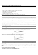
IDENTIFYING EXTERNAL COMPONENTS This chapter describes the front panel, rear panel, and LED indicators of the Switch. Front Panel The figure below shows the front panels of the Switch. Figure 3. Front panel of 48+2G-port Gigabit Ethernet Switch LED Indicator: Comprehensive LED indicators display the status of the Switch and the network (see the LED Indicators chapter below).
UNDERSTANDING LED INDICATORS The front panel LEDs provide instant status feedback, and help monitor and troubleshoot when needed. Figure 5. LED indicators of the Switch Power and System LEDs POWER: Power Indicator On : When the Power LED lights on, the Switch is receiving power. Off : When the Power turns off or the power cord has improper connection. CPU: Management Indicator Blinking : When the CPU is working, the System LED is blinking. On/Off : The CPU is not working.
On (Amber) Off When the Amber light is on, the respective port is connected to a 100Mbps Fast Ethernet network. : When the respective port is connected to a 10Mbps Ethernet or No link. Ports 49~ 50 mini-GBIC Status LEDs Link/ACT: Link/Activity On : When the mini-GBIC transceiver is installed and connected to a network, the Link/ACT LED lights on. Blinking : When the LED is blinking, the mini-GBIC module is receiving data on a network. Off : No link.
CONFIGURATION Through the Web Browser you can configure Switch settings such as VLAN, Trunking, QoS… etc. With the attached Web Management Utility, you can easily discover all Web Management Switches, assign the IP Address, change the password, and upgrade new firmware. Installing the Web Management Utility "If your utility is old version, please remove it and install v.1.01 or higher" The following provides instructions guiding you through the installation of the Web Management utility. 1.
z z z Trap IP: Shows the IP where the Trap is to be sent. Subnet Mask: Shows the Subnet Mask set of the device. Gateway: Shows the Gateway set of the device. Monitor List All the Web Smart Devices in the Monitor List can be monitored; you can also receive traps and show the status of the device. System word definitions in the Monitor List: z z z z z z z z z z S: Shows the system symbol of the Web-Smart device, IP Address: Shows the current IP address of the device.
The factory default password is "admin." Figure 9. Configuration Setting Password Change: You can use this Password Change when you need to change the password, fill in the required passwords in the dialog box and press the “Set” button to process the password change immediately. Figure 10. Password Change Firmware Upgrade: When the device has a new function, there will be a new firmware to update the device; use this function to upgrade the firmware. Figure 11.
In the “Option TAB”, there is the Refresh Time function; this function helps you to refresh the time for monitoring the device. Choose 15 secs, 30 secs, 1 min, 2 min, and 5 min to select the time for monitoring. In the “Help TAB”, there is About function, it will show out the version of the Web Management Utility. Configuring the Switch The 48+2G-Port 10/100/1000Mbps Gigabit Ethernet Web Smart Switch has a Web GUI interface for smart switch configuration.
Figure 14. Device Status Setup Menu When the main page appears, find the Setup menu on the left side of the screen (Figure 15). Click on the setup item that you want to configure. There are eleven options: Port Settings, VLAN Settings, Trunk Setting, Device Status, Statistic, System Settings, Trap Setting, Password Setting, Backup Setting, and Reset Setting as shown in the Main Menu screen. Figure 15.
Figure 16. Port Configuration To change the port setting, click on the ID parameter to enter the selected port to configure its Speed/Disable, Flow control, and QoS setting. Figure 17. Speed: This setting has six modes—1000M Full, 100M Full, 100M Half, 10M Full, 10M Half, Auto, and Disable—for speed or port disable selections. Note: If the speed set to 100M full mode or 10M full mode, flow control should have the fixed setting set to disable.
VID group and press the “Remove the VID” button. To modify the VID group setting, select the VID group and change the setting, and press the “Apply” button to save the settings. Figure 18. When you select Port VLAN setting, fill in each port’s PVID value between 1 and 4094. Figure 19. Trunk Setting The Trunk function enables the Switch to cascade two devices with a double times bandwidth (up to 4000Mbps in full-duplex mode).
Figure 1. Mirror setting Be sure that the selected trunk setting port connects to the device with a same VLAN group. Device Status Click on the “Status” button to present the device status on this screen, it will show the System Status, Port Status, VLAN Status, and Trunk Status. Press “Refresh” when you need to renew the posted information. Statistic The Statistic Menu screen will show the status of each port packet count. Figure 23.
System Setting The System Setting includes the System name, Location name, Login Timeout, IP Address, Subnet Mask, and Gateway. Through the Web Management Utility, you can easily recognize the device by using the System Name and the Location Name. The Login Timeout is used to set the idle time-out for security purposes. When there is no action while running the Web Smart Utility and the time is up, you must re-login to Web Smart Utility before you set the Utility.
To restore a current setting file to the device, you must specify the backup file and press the “Restore” button to process the setting of the recorded file. Figure 28. Backup Setting Note: When restoring a recorded file, the current password will not be erased. Reset Setting The Factory Reset button helps you to reset the device back to the default setting from the factory. Be aware that the entire configuration will be reset; the IP address of the device will be set to the default setting of 192.168.0.
TECHNICAL SPECIFICATIONS General Standards IEEE 802.3 10BASE-T Ethernet IEEE 802.3u 100BASE-TX Fast Ethernet IEEE 802.3z 1000BASE-SX/LX Gigabit Ethernet IEEE 802.3ab 1000BASE-T Gigabit Ethernet IEEE 802.3x Full Duplex Flow Control Protocol CSMA/CD Data Transfer Rate Ethernet: 10Mbps (half-duplex), 20Mbps (full-duplex) Fast Ethernet: 100Mbps (half duplex), 200Mbps (full-duplex) Gigabit Ethernet: 2000Mbps (full-duplex) Topology Network Cables Star 10BASET: 2-pair UTP Cat.
Subject to the terms and conditions set forth herein, D-Link Systems, Inc. (“D-Link”) provides this Limited Warranty: • • Only to the person or entity that originally purchased the product from D-Link or its authorized reseller or distributor, and Only for products purchased and delivered within the fifty states of the United States, the District of Columbia, U.S. Possessions or Protectorates, U.S. Military Installations, or addresses with an APO or FPO.
Limitation of Liability: TO THE MAXIMUM EXTENT PERMITTED BY LAW, D-LINK IS NOT LIABLE UNDER ANY CONTRACT, NEGLIGENCE, STRICT LIABILITY OR OTHER LEGAL OR EQUITABLE THEORY FOR ANY LOSS OF USE OF THE PRODUCT, INCONVENIENCE OR DAMAGES OF ANY CHARACTER, WHETHER DIRECT, SPECIAL, INCIDENTAL OR CONSEQUENTIAL (INCLUDING, BUT NOT LIMITED TO, DAMAGES FOR LOSS OF GOODWILL, LOSS OF REVENUE OR PROFIT, WORK STOPPAGE, COMPUTER FAILURE OR MALFUNCTION, FAILURE OF OTHER EQUIPMENT OR COMPUTER PROGRAMS TO WHICH D-LINK’S PRODUCT
Product Registration Register online your D-Link product at http://support.dlink.com/register/ Product registration is entirely voluntary and failure to complete or return this form will not diminish your warranty rights.
International Offices U.S.A 17595 Mt. Herrmann Street Fountain Valley, CA 92708 TEL: 1-800-326-1688 URL: www.dlink.com Canada 2180 Winston Park Drive Oakville, Ontario, L6H 5W1 Canada TEL: 1-905-8295033 FAX: 1-905-8295223 URL: www.dlink.ca Europe (U. K.) 4th Floor, Merit House Edgware Road, Colindale London NW9 5AB U.K. TEL: 44-20-8731-5555 FAX: 44-20-8731-5511 URL: www.dlink.co.uk Germany Schwalbacher Strasse 74 D-65760 Eschborn Germany TEL: 49-6196-77990 FAX: 49-6196-7799300 URL: www.dlink.de France No.