DAP-3760 / DAP-3860 Broadband Wireless Access ODU Quick Installation Guide
Copyright Copyright © 2008 all rights reserved. No part of this publication may be reproduced, adapted, stored in a retrieval system, translated into any language, or transmitted in any form or by any means without the written permission of the supplier. About the Installation Guide This Installation Guide is intended to guide professional installer to install the wireless bridge. It includes procedures assisting you in avoiding unforeseen problems.
Federal Communication Commission Interference Statement This equipment has been tested and found to comply with the limits for a Class B digital device, pursuant to Part 15 of the FCC Rules. These limits are designed to provide reasonable protection against harmful interference in a residential installation. This equipment generates, uses and can radiate radio frequency energy and, if not installed and used in accordance with the instructions, may cause harmful interference to radio communications.
This transmitter must not be co-located or operating in conjunction with any other antenna or transmitter. The availability of some specific channels and/or operational frequency bands are country dependent and are firmware programmed at the factory to match the intended destination. The firmware setting is not accessible by the end user. Professional Installation Required 1.
TABLE OF CONTENT Professional Installation Required ...................................................................................................2 CHAPTER 1 INTRODUCTION...........................................................................................................5 INTRODUCTION......................................................................................................................................5 PRODUCT SPECIFICATION ..........................................................
BASIC SETTINGS ..................................................................................................................................24 IP Address.......................................................................................................................................25 Operating Mode..............................................................................................................................25 Base Station ID..........................................................
Chapter 1 Introduction Introduction The DAP-3760 / DAP-3860 Wireless Bridge is a high-performance outdoor-deployable wireless bridge that provides wireless connectivity among multiple network locations. Besides the built-in 23dBi plane antennas, it can cover over 50km if with an external antenna co-used, answering the demand of long distance backhaul with high throughput.
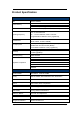
Product Specification Specifications CPU System Memory Power IXP425 ,533MHz 16MB Flash 32MB SDRAM (64MB upgradable) Power over Ethernet (Output 20Watts ,48V /0.4A) FCC : 5.725~5.850 GHz Operating Frequency CE : 5.470~5.600 GHz, 5.650~5.725 GHz (Programmable for different country regulations) RF Modulation RF output power 802.11a: OFDM (BPSK, QPSK, 16-QAm, 64QAM) 24dBm (Max. of Avg.
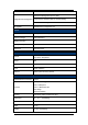
Link Test Self-Wireless Connection test Web-based Management (Secure SSL) Configuration & Management Command Line Interface (SSH or RS-232 (9600)) Windows-based Utility, SNMPv2 FW Upgrade Web/Windows management tool Antenna Gain 23dBi (Default for FCC) Frequency Range 5400~5850 MHz HPBW (horizontal) 10° HPBW (vertical) 10° Dimensions 320×320×18mm Physical & Interface Ethernet 10/100 Base T x1 Auto-sense, Negotiation RS-232 YES USB N/A Buzzer Signal Indication Reset Pin Reset system to
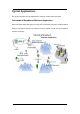
Typical Applications This section describes the typical applications centering on DAP-3760 / DAP-3860. Tele-medical Broadband Wireless Application DAP-3760 / DAP-3860 mainly plays as a relay with cost-effective solar power, sending medical treatment information between city hospital and local hospital in rural area via broadband wireless connectivity.
Campus Broadband Wireless Application Campus in remote area can access to the Internet via broadband wireless connectivity established by DAP-3760 / DAP-3860 which plays as relay and CPE.
Chapter 2 Preparation before Installation This chapter describes safety precautions and product information you have to know and check before installing DAP-3760 / DAP-3860.
Note: Product CD contains Management Tool, Quick Installation Guide and User Manual! Mounting Kit Wall/Pole Mounting Bracket 1. T-Form Bracket ×1 2. Articulation Pole ×1 3. Pole Mount Bar ×1 Fasteners 4. M8×110 Screw ×3 5. M8 Washer ×3 6. M8 Spring Washer ×3 7. M8 Nut ×1 8. M5×12 Screw ×4 9. M5 Washer ×4 10. Wood Screw ×4 11. Wall/Gyprock Plug ×4 Waterproof RJ-45 Connector Kit 1. Gland ×1 2. Sealing Nut ×1 3.
Site Planning Prior to installation, develop a checklist that covers all aspects of the installation. A well-developed plan identifies potential problems early so that they can be solved timely. Choosing a Mounting Location Choosing a good mounting location for the bridge is important because it affects the reliability of the wireless link and maximum data rates the bridge system can achieve. The most important considerations are distance between bridges and clearance from obstacles.
The Fresnel Zone is important to the wireless link as it defines an area around the LoS that can introduce RF signal interference if blocked. Objects in the Fresnel Zone such as trees and buildings can diffract or reflect the main signal away from the receiver, changing the RF LoS. Antenna Polarization The integrated antenna radiates and receives polarized radio signals.
Chapter 3 Hardware Installation The DAP-3760 / DAP-3860 Wireless Bridge is shipped with mounting hardware that accommodates tower or mast installations. This chapter demonstrates the hardware installation procedures, which include Assemble the Hardware Mounting, Pole Mounting, Connect Up, Ground the Wire, Power On and Align the Antennas. Assemble the Mounting Bracket 1.
Pole Mounting 1. Install the main bracket and the pole mount bar over the top of the pole by securing the drill holes of the pole mount bar to the main bracket ones and insert two M8×110 screws, spring washers and washers through the drill holes and main bracket; 2. Fasten two M8×110 screws and washers through the drill holes and main bracket with a spanner; 3. Adjust the antenna for appropriate tilt / vertical orientation.
Interface Definition DAP-3760 / DAP-3860 currently provides two interfaces at the bottom, which are PoE & Data with a black plastic dummy cover and RS-232 with a white dummy cover. Among which, a black RJ45 waterproof connector will be provided for the PoE & Data interface. RS-232 RS-232 is used for debugging purposes as well as for hard reset of the DAP-3760 / DAP-3860. Below you may find the pin definition of the RS-232.
To reset the device, short P7 (Hard Reset) to P8 (GND) for less than 1 second and the system will reset. If P7 (Hard Reset) is shorted to P8 (GND) for over 5 seconds, the DAP-3760 / DAP-3860 will be reset to the factory default settings.
Connect Up Before installing the Ethernet cable with a waterproof RJ-45 connector, it is recommended that the Cat-5 RJ-45 coaxial cable be used for the DAP-3760 / DAP-3860 to power injector connections. 1. To connect to the hole labeled PoE+Data, open the black cover in advance by using a coin or a slotted screwdriver and then screw in the body of the gland and tighten. Connect Up – Step 1 2. Slide the sealing nut to the RJ-45 cable from its middle breach and then insert the sealing into the cable.
Screw the sealing on the gland and tighten. Connect Up – Step 4 Grounding The DAP-3760 / DAP-3860 is shipped with a grounding wire. The unit must be properly grounded to protect against power surges. The DAP-3760 / DAP-3860 grounding point can be found on the bottom of the unit. It is supplied with an appropriate grounding lug for attachment to the ODU. Ground the Wire. Grounding Power on To power up the DAP-3760 / DAP-3860, follow the steps bellow: 1.
2. Plug a user-supplied Cat-5 Ethernet cable from the DAP-3760 / DAP-3860 into the power injector RJ-45 jack (P+DATA OUT); 3. Connect the power module to the power injector and plug the AC cord into an AC power receptacle; 4. After being powered on, the device will send out the beep sound lasting about 1.5 seconds, informing you that the DAP-3760 / DAP-3860 is powered up! Wait for about 60 seconds the system will be initialized and start working. 1.
Align Antenna After powering up the wireless bridge, align the integrated antenna to point in the approximate direction of the remote bridge antenna. If the antenna is at a significant angle, use binoculars, satellite global positioning system (GPS) or reference objects to detect the remote bridge or antenna, and then manually adjust the horizontal and vertical positions accordingly. To verify whether the two antennas are correctly pointed to each other, ping the remote wireless bridge.
3. After the two integrated antennas are well positioned, secure the bridge mounting fasteners. The bridges now are ready to be configured and incorporated into your network.
Chapter 4 Configuration The units to be installed should be configured before physical installation. During this process, the installer can set the unit’s IP address to the one within desired address range and set each unit up with the MAC address of its peer unit ready to establish a wireless link. It is recommended that this procedure be carried out on the bench before physical installation. This chapter describes how to configure your bridge for the first time.
3. Enter the user name (admin) and password (password) to login and make configurations. 4. After configuring the bridge, remove the Ethernet cable from PC and connect the power injector back to your wired LAN port. Basic Settings After login to the Web-based management interface, you will see the “About” page as below. Click “Basic” in the left menu bar to make basic system configurations.
IP Address Enter the settings obtained from your system administrator. The most important setting is IP Address. You may manually assign an IP address or check “DHCP” to automatically obtain one from DHCP server on your network.
CPE Under this mode, the bridge connects to a remote LAN and that Base Station. Select “Multicli” or “LAN-to-LAN” for your network application and specify the SSID of the corresponding Base Station.
Peer to Peer (CSMA) Under peer-to-peer (CSMA) mode, set the same channel for all the peer units. Open “Peer-to-Peer Links” (as below) page to enter the MAC address of the remote peer unit. Peer to Peer (TDMA) Under peer-to-peer (TDMA) mode, set one group ID for all the peer units.
Base Station ID The SSID is a unique identifier that bridges use to associate to each other. It is case-sensitive and consists of no more than 32 alphanumeric characters. By default, it is set to “Wireless”. Output Power If the bridges are installed less than 328ft (100m) apart, the output power should be adjusted lower to avoid overloading the bridge’s receivers. To configure the output power, open “Radio” and select the appropriate output power value: Full, Half, and Quarter.
Alternatively, under “Base Station” mode, by clicking “Edit”, the “Security Profile Configuration” window will popup. You can set the SSID and security configuration here. Network Authentication Type Open System: It allows any device to join the network without performing security check.
Shared Key: Encryption strength and key are required. WPA-PSK: No need for specific authentication server. In this so-called WPA Pre-Shared Key, all you have to do is just pre-enter a key in each WLAN node and this is the common way to be adopted in large and middle enterprise as well as residential network. WPA2-PSK: Only all the clients support WPA2, can it be available. If it is selected, the data encryption type must be AES and the passphrase is required.
Chapter 5 Troubleshooting This chapter provides troubleshooting procedures for basic problems with the bridge. Q 1. What if my bridge fails to connect to the remote one? • Ethernet Link: Check the availability of power to the bridge by observing the LED status on the power injector. - Green: The wireless bridge is connecting to the backhaul network.
Chapter 6 Technical Support If you still have any trouble using the wireless bridge or you would like to require additional support, please check the following information for support: Z-Com, Inc. Taiwan 7F-2, No.9. Business RD. Center Industrial Park FAE Support Hsinchu ,300 Taiwan support@zcom.com.tw I Prosperity Tel: +886-3-5777364 Sales Contact Science-Based Fax:+886-3-5773359 info@zcom.com.tw Zcomax Technologies, Inc. California 14545 Valley View Ave.