Table of Contents Package Contents .......................................................................................................................................................................................................................................1 Minimum System Requirements..................................................................................................................................................................................................................
1) Identify Your Camera on the Network .....................................................................................................................................................................................42 2) Assign a Local IP Address and Port for Your Camera ............................................................................................................................................................43 3) Open the HTTP Port ......................................................
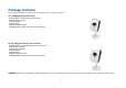
Package Contents If any of the below items are missing from your package, please contact your retailer.
Minimum System Requirements Wired (10/100 Fast Ethernet) network Wireless 802.11g network (for DCS-2121 only, for wireless use only) PC with: 1.3 GHz processor or higher 128 MB memory or more Windows XP SP2 or Vista Internet Explorer 6 or higher Multiple camera operation requires: 2.4 GHz processor or higher 512 MB memory or more Video card/chipset with 32 MB RAM Windows XP SP2 or Vista Internet Explorer 6 or higher Wireless use requires (DCS-2121 only): 802.
Introduction Congratulations on your purchase of the DCS-2102/2121 Megapixel Internet Camera! The DCS-2102/2121 is a versatile and unique solution for your small office or home. Unlike a standard webcam, the DCS-2102/2121 is a complete system with a built-in CPU and web server that transmits high quality video images for security and surveillance. The DCS-2102/2121 can be accessed remotely, and controlled from any PC/Notebook over local network or through the Internet via a web browser.
Features and Benefits Simple to Use: The DCS-2102/2121 is a stand-alone system with a built-in CPU, requiring no special hardware or software such as PC frame grabber cards. The DCS-2102/2121 supports ActiveX mode for Internet Explorer. All that is required is a computer with Internet Explorer 6.0 or above. Supports a Variety of Platforms: Supports TCP/IP networking, HTTP, and other Internet related protocols.
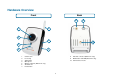
Hardware Overview Front Back 8 1 9 5 2 6 10 3 4 7 1. 2. 3. 4. 5. 6. 7. Camera lens Focus ring Status LED Microphone Wireless antenna (DCS-2121 only) SD Card slot Reset button 8. Antenna connector (DCS-2121 only) 9. WPS button and LED (DCS-2121 only) 10.
Bottom 1 1. 2. 3. 4.
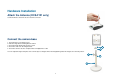
Hardware Installation Attach the Antenna (DCS-2121 only) Screw the wireless antenna onto the antenna connector. Connect the camera base 1. Screw the base stem into the base. 2. Take the hinge bracket and tighten the wheel. 3. Screw the hinge bracket into the base stem. 4. Screw the collar onto the hinge bracket. 5. Screw the camera onto the completed base and tighten the collar.
Connect the Ethernet Cable Connect the included Ethernet cable to the network cable connector located on the bottom of the DCS-2102/2121 and attach it to your network switch or router. Connect the Power Adapter Attach the power adapter to the power jack located on the bottom of the DCS-2102/2121 and connect the power adapter to a power outlet. After connecting the power adapter, you should see the Status LED on the front of the camera turn on.
Autorun Installation Insert the Installation CD-ROM into your computer’s CD-ROM drive to initiate the autorun program. The content of the Installation CD-ROM includes: View QIG: Click here to view the Quick Installation Guide for a quick step-by-step guide to installing the DCS-2102/2121. View Manual: Click here to view the User Manual for detailed information about the DCS-2102/2121. Installation Wizard: Click here to install the DCS-2102/2121’s initial configuration software.
Software Installation Click the Installation Wizard button from the autorun program on the CD. Follow the simple steps below to run the Setup Wizard to guide you quickly through the installation process. Click Next.
Click Yes. Click Next. Click Finish.
Now, click on ffdshow from the autorun screen. This will install the proper codecs that will allow you to playback video taken by the DCS-2102/2121. Click I Agree. Click Next.
Click Install. Click Close.
Before using ffdshow, you must configure its properties. From your computer, please click on Start Programs ffdshow Configuration. At the ffdshow properties window, scroll to the bottom and click Miscellaneous. Be sure that Autodetect is checked and that Error resilience and Error concealment are set to “none”. Click OK and close the window.
To run the Setup Wizard, click on Start Programs D-Link Setup Wizard SE. The Setup Wizard will then scan for all available cameras connected to your wired network. Each camera will appear with its MAC address, current IP address, and camera name. You can choose from the following options from the buttons on the left: Wizard: Search: Link: About: Exit: This will guide you through initial network setup of the selected camera.
Here, you can set whether the camera should use a direct or static IP. If you use a static IP, the camera's IP Address, Subnet Mask, Gateway, and DNS addresses must correspond with your network settings for you to access the camera. If you are unsure of what these settings should be, please check with your network administrator or Internet service provider. After entering your settings, click Next.
If you need to make any changes, click Back to modify your camera settings. Otherwise, click Restart to save and apply your settings. This may take a few minutes. (Wireless settings are for DCS-2121 only) Camera setup is now complete! Wait until the Link LED on the camera turns green, then click Link to launch your Web browser and view your images.
After you click the Link button, the Installation Wizard will automatically open your Web browser to the IP address of the DCS-2102/2121 and prompt you for a user name and password. Enter “admin” into the User name field, then click OK. If you changed your password in the Setup Wizard, enter your password then click OK. After you successfully log in, your camera’s video will be displayed inside the web browser window.
Adjusting the Camera Focus After opening the web interface, turn the focus ring left or right until the area you want to view is in focus. You can use the video feed of the web interface as a guide. Note: You can adjust other settings such as brightness, contrast, orientation in the SETUP > Image Setup section of the web interface. Warning: Direct exposure to sunlight may cause permanent damage to the CMOS sensor. Therefore, do not expose the DCS-2102/2121’s lens to direct sunlight.
Setting up a Wireless Connection with WPS (DCS-2121 only) If your wireless access point or router supports push-button Wireless Protected Setup (WPS), you can quickly configure your wireless network and camera without using the camera’s web interface. After plugging the power adapter to your camera and the front status LED lights up, hold down the WPS button on the back of the camera for 3 seconds. After pressing the button, it should start flashing blue.
Using the Configuration Menu After completing the Setup Wizard, you are ready to use your camera. The Web configuration utility is designed to easily access and configure your DCS-2102/2121. Click the “Link” button will open up the main configuration page. If you would like to open the configuration page from a Web Browser, enter the IP address that you assigned to your DCS-2102/2121. In this example, the IP address of the camera is 192.168.0.20.
LIVE VIDEO This section allows you to set up your IP camera's live video by using the buttons below. LIVE VIDEO > Camera Screen Size: You can change the video screen size to Small, Medium, or Large. Full Screen: This allows you to view the video in full screen mode. To exit full screen mode, press the ESC key on your keyboard. Snapshot: Click it to capture a snapshot image. The image will pop up in a new window. Then you may save this image to a local hard drive.
SETUP This section allows you to further set up or change the configuration of your IP camera. SETUP > Wizard The setup wizards guide you through initial setup of your IP camera. You can use the Internet Connection Setup Wizard for initial network setup, and you can use the Motion Detection Setup Wizard to set up motion detection and snapshots. Simply follow the instructions given in each step of the wizard to quickly set up your camera.
SETUP > Network Setup This option, Network Setup, allows you to configure your LAN and Internet configuration, including the settings for LAN, PPPoE, and port. DHCP Connection: This allows the camera to get an IP address automatically from your router or Internet service. If you are not sure which LAN settings to use, try using DHCP mode first. Static IP Address: This allows you to manually set the IP address information for your camera. This may be required to connect to your Internet connection.
SETUP > Wireless (DCS-2121 only) To set up your IP camera's wireless network interface settings, enable Wireless Settings in this window first. Then continue the further configuration next. Site survey: Clicking this button will scan for available wireless networks. After scanning, you can use the dropdown box to select an available wireless network, and related information(SSID, Wireless Mode, Channel, Authentication, Encryption) will be automatically filled in for you.
SETUP > Dynamic DNS If you have a DSL or Cable service provider that changes your modem IP address periodically, Dynamic DNS (Domain Name Service), a method of keeping a domain name linked to a dynamic IP address, is useful. With most Cable and DSL connections, you are assigned a dynamic IP address and that address is used only for the duration of that specific connection.
SETUP > Image Setup The options in Image Setup allow you to adjust the settings for your IP camera sensor and image. Brightness: This adjusts the brightness of the camera image. This is set to 60 by default. Saturation: This adjusts the color saturation of the camera image. This is set to 60 by default. Contrast: This adjusts the contrast of the camera image. This is set to 0 by default.
SETUP > Audio and Video This Audio and Video option allows you to set up your IP camera’s video quality, resolution, and frame rate. Video Sensor Sensor Output: You can set the camera's sensor output to VGA quality (640x640), XGA quality (1024x768), or SXGA quality (1280x1024). Note: When using SXGA mode, please note that motion detection and motion triggered snapshots will be disabled and that recordings will be done at a maximum of Medium resolution.
Note: Higher frame size, frame rate and bit rates will give you better video quality, but they will also require more network bandwidth. For best viewing results on a mobile phone, we suggest setting the Frame Rate to 5 fps and bit rate to 20 Kbps. After making any changes, click the Save Settings button to save your changes, or click the Don’t Save Settings button to discard your changes.
SETUP > Motion Detection This option allows you to set up Motion Detection on your IP camera. In order to use motion detection you must first check the Enable Video Motion checkbox. You can then click on the video window and draw motion detection zones by clicking and dragging your mouse. Red areas indicate areas that will be monitored for motion.
SETUP > Time and Date This option allows you to configure, update, and maintain the correct time on the internal system clock. From this section you can set the time zone that you are in and set the NTP (Network Time Protocol) Server. Daylight Saving can also be configured to automatically adjust the time when needed. Time Zone: Select your time zone from the drop down menu. Enable Daylight Saving: If your region uses a Daylight Saving adjustment, check this checkbox.
SETUP > Recording This option allows you to configure recording settings and scheduling. You can record video to a Secure Digital card inserted into the SD card slot, or you can have video saved to a Samba network drive. Enable recording: Check this checkbox to enable the recording feature. After enabling recording, you will need to select a location to record to (SD Card or Samba network drive), and you will need to select a scheduling method.
Scheduling Event Based: Event based recording will allow you to record video when specific events happen. Motion detection triggered recording: Enabling this option will set the camera to record video when motion is detected by the camera. Digital input triggered recording: When the camera receives a signal from its DI input, it will start recording. You can find more information about the DI/DO interface at the end of this document.
SETUP > Snapshot Here, you can set the camera to take snapshots when motion is detected and/or when a signal is sent to the DI input. Snapshots can be sent to an e-mail address and/or to an FTP server. Enable Snapshot: Check this box to enable the snapshot feature. Trigger Event: Motion detection: This will set the camera to take a snapshot whenever motion is detected. D/I: This will set the camera to take a snapshot whenever a signal is sent to the D/I input.
SETUP > Digital Output This screen allows you to enable the Digital Out (D/O) port, and allows you to select what events will trigger the Digital Out signal. Enable D/O: Check this box to enable the D/O port. Motion Detection: When checked, the D/O port will send a signal whenever motion is detected by the camera. (When motion detection has been enabled) D/I: When checked, the D/O port will send a signal whenever a signal is detected on the Digital In (D/I) port.
MAINTENANCE MAINTENANCE > Device Management Here you can change the Admin password, add and manage Users, and adjust some camera settings. Admin Password Setting: This section lets you change the admin password used to log in to the camera and adjust settings. After installing the camera for the first time, it is highly recommended that you change the admin password for security purposes. New Password: Enter the new admin password to use. Retype Password: Enter the new admin password again for verification.
MAINTENANCE > Backup and Restore This screen llows you to save and restore the camera’s current configuration. You can also reset all settings to factory default, and reboot the device. Save To Local Hard Drive: Click on the Save Configuration button to save the current configuration to a hard drive.
MAINTENANCE > Firmware Upgrade Here, you can see your current firmware version and you can also upgrade your firmware with a new version. Firmware upgrades are made available at support.dlink.com.tw. To upgrade your firmware, go to support.dlink.com.tw and download the latest firmware to your computer’s hard drive. Click on Browse…, select the firmware file, then click the Upload button.
STATUS The Status section provides the detail information about your IP camera. STATUS> Device Info This screen shows you various information about your camera and its current settings.
STATUS> Log The log shows you a list of events that have happened recently. You can download the log by clicking the Download button, or you can empty the log by clicking the Clear button.
HELP The Help screen provides you with support information about the DCS-2102/2121 for your reference.
Installing the DCS-2102/2121 Behind a Router If you connect your cameras to an Internet router, follow these steps to allow remote access to your cameras, so you can access your cameras from any Internet-connected PC: 1) Identify your camera on the network 2) Assign a local IP address and port for your camera 3) Determine your router’s WAN IP Address (Enable Remote Viewing) 4) Open virtual server ports for your router (Enable Remote Viewing) 1) Identify Your Camera on the Network Log into your camera’s w
2) Assign a Local IP Address and Port for Your Camera Click on the SETUP tab, and select Network Setup A Local IP Address is required to configure your camera and to view your camera within your local network. You may use the default camera IP Address of 192.168.0.20. If you wish to use a different IP Address, be sure that the camera settings correspond to your network settings. The Default Gateway will be the IP Address of your router’s Local IP Address (e.g.192.168.0.
3) Open the HTTP Port The HTTP Port option is used when multiple cameras are being installed behind a single public IP address and will be accessed remotely OR for using a port other than the default port for image viewing. For each additional camera that is installed, you must assign the appropriate Web server port for each camera to enable remote viewing. By default, port 80 (Web server port) is open.
Router Setup The following steps generally apply to any router that you have on your network. The D-Link DIR-300 is used as an example to clarify the configuration process. Your WAN IP Address information will be listed on following window. Note: Because a dynamic WAN IP address can change from time to time depending on your ISP, you may want to obtain a Static IP address from your ISP.
4) Open Virtual Server Ports to Enable Remote Image Viewing The Virtual Server Ports of your router must be opened for remote access to your camera. This is also referred to as port forwarding. Please proceed as follows: Select Enabled to enable virtual server settings. Select a camera name. Enter your camera’s Local IP Address in the private/local IP field. Select TCP under Protocol Type. Enter 80 for your public port, and whatever port your camera's HTTP port is set to use (80 is the default).
Viewing Your Camera Over the Internet After all settings have been entered correctly, a user inside or outside your network will have access to the camera through a standard Web browser. To access your camera, simply type in the IP Address of the router given to you by your ISP, a colon, and the HTTP port number that you gave your camera.
Frequently Asked Questions Internet Camera Features 1 What is an Internet Camera? An Internet Camera is a standalone system that connects directly to an Ethernet or Fast Ethernet network and supported by the wireless transmission based on the IEEE 802.11g standard, whereas conventional PC Cameras require connection to a powered PC to function. An Internet Camera is an all-in-one system with a built-in CPU, providing a low cost web-based solution that can transmit high quality video images for monitoring.
10 Why can’t I access the Internet Camera from a web browser? A possible cause might be that the IP Address for the Internet Camera is already being used by another device. To correct the possible problem, you need to first disconnect the Internet Camera from the network. Then try to PING (follow the instructions in the section titled How to PING Your IP Address:) the IP address your Internet Camera is set to use.
18 Why are no images available through the Web browser? ActiveX might be disabled on your web browser. If you are viewing the images from Internet Explorer, make sure ActiveX has been enabled in the Internet Options menu. You may also need to change the security settings on your browser to allow the ActiveX plug-in to be installed.
How to Ping Your IP Address The PING (Packet Internet Groper) command can determine whether a specific IP Address is accessible by sending a packet to the specific address and waiting for a reply. It is a very useful tool to confirm if the IP Address conflicts with the Internet Camera over the network. Follow the step-by-step procedure below to utilize the PING command. • Start a DOS window Start Program Accessories Command Prompt. • Type ping x.x.x.x, where x.x.x.
If you fail to connect to your camera you will see the following: Check to see if you have entered your camera’s IP Address correctly or reassign your camera’s IP Address.
Time Zone Table (GMT -12:00) International Dateline West (GMT -11:00) Midway Island, Samoa (GMT -10:00) Hawaii Island (GMT -09:00) Alaska (GMT -08:00) Pacific Time (US & Canada); Tijuana (GMT -07:00) Mountain Time (US & Canada) (GMT -06:00) Central Time (US & Canada) (GMT -05:00) Eastern Time (US & Canada) (GMT -04:00) Atlantic Time (Canada) (GMT -03:00) Buenos Aires, Georgetown (GMT -02:00) Mid-Atlantic (GMT -01:00) Cape Verde Is.
DI/DO Input specifications DO Digital Output: Normal: open circuit Trigger: short circuit After powering on or rebooting the DCS-2121, the camera will be in Normal mode by default. DI Digital Input: Normal: no current Trigger: 12V current As the Digital Input signal is controlled by an external device, we recommend that you set your device to feed no current normally, and feed a 12V current only to trigger a DI event on the DCS-2121.
Technical Specifications Video Codec MPEG-4 / MJPEG Audio Codec GSM-AMR: 8kbps, ADPCM: 8Kbps Sensor 1/4" color 1.3MP CMOS sensor SDRAM 64 Mbytes Flash Memory 8 Mbytes SD-Card Slot Supports SD Cards up to 16GB Lens 5.01mm, F2.8 LAN • 10/100BASE T port • IEEE 802.3 compliant • IEEE 802.3u compliant • Supports Full-Duplex operation • MDI/MDIX auto-negotiation • 802.
Audio Out Yes Reset Button Reset to factory default Dimension (WxDxH) 71.9mm x 110.0mm x 37mm (without bracket and stand) Weight DCS-2121: 281.4g (without bracket and stand) DCS-2102: 265.3g (without bracket and stand) Max Power Consumption • 6W • Input: 100-240VAC, 50/60Hz • Output: 5VDC, 2.5A Networking Protocol • IPV4, ARP, TCP, UDP, ICMP • DHCP Client • NTP Client • DNS Client • DDNS Client • SMTP Client • FTP Client • HTTP Server • Samba Client • PPPoE • RTP • RTSP • RTCP • 3GPP Connectivity • 802.
Video Algorithm Supported • MPEG-4/MJPEG simultaneous dual-format compression • JPEG for still image Features • Adjustable image size and quality • Time stamp and text overlay • Configurable motion detection zones Resolution 1.3M: 1280 x 1024 at up to 10fps 1024 x 768 / 512 x 384 / 256 x 192 at up to 10fps 300K: 640 x 480 / 320 x 240 / 160 x 120 at up to 30fps Low Lux 0.5 lux @ F2.
OS Support Device Windows 2000 / Windows XP / Windows Vista / 3GPP Mobile Phone Utility Windows 2000 / Windows XP / Windows Vista Physical Environment Power • 5V 2.