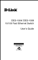
DES-1004/ DES-1008 10/100 Fast Ethernet Switch User’s Guide Rev. 01 (May, 1997) 6DES1008..
Wichtige Sicherheitshinweise 1. Bitte lesen Sie sich diese Hinweise sorgfältig durch. 2. Heben Sie diese Anleitung für den spätern Gebrauch auf. 3. Vor jedem Reinigen ist das Gerät vom Stromnetz zu trennen. Vervenden Sie keine Flüssig- oder Aerosolreiniger. Am besten dient ein angefeuchtetes Tuch zur Reinigung. 4. Um eine Beschädigung des Gerätes zu vermeiden sollten Sie nur Zubehörteile verwenden, die vom Hersteller zugelassen sind. 5. Das Gerät is vor Feuchtigkeit zu schützen. 6.
WARRANTIES EXCLUSIVE IF THE D-LINK PRODUCT DOES NOT OPERATE AS WARRANTED ABOVE, THE CUSTOMER'S SOLE REMEDY SHALL BE, AT D-LINK'S OPTION, REPAIR OR REPLACEMENT. THE FOREGOING WARRANTIES AND REMEDIES ARE EXCLUSIVE AND ARE IN LIEU OF ALL OTHER WARRANTIES, EXPRESSED OR IMPLIED, EITHER IN FACT OR BY OPERATION OF LAW, STATUTORY OR OTHERWISE, INCLUDING WARRANTIES OF MERCHANTABILITY AND FITNESS FOR A PARTICULAR PURPOSE.
Limited Warranty Hardware: D-Link warrants its hardware products to be free from defects in workmanship and materials, under normal use and service, for the following lengths of time from the date of purchase from D-Link or its Authorized Reseller: Product Type Unmanaged Ethernet Switch Managed Ethernet Switch Warranty Period Lifetime Three years If a product does not operate as warranted during the applicable warranty period, D-Link shall, at its option and expense, (1) repair the defective product or pa
Software: D-Link warrants that the software programs licensed from it will perform in substantial conformance to the applicable published program specifications for a period of ninety (90) days from the date of purchase from DLink or its Authorized Reseller. D-Link warrants the magnetic media containing software against failure during the warranty period. No updates are provided.
Trademarks Copyright 1996 D-Link Corporation. Contents subject to change without prior notice. D-Link is a registered trademark of D-Link Corporation/D-Link Systems, Inc. All other trademarks belong to their respective proprietors. Copyright Statement No part of this publication may be reproduced in any form or by any means or used to make any derivative such as translation, transformation, or adaptation without permission from D-Link Corporation/D-Link Systems Inc.
T ABLE OF C ONTENTS 0 ABOUT THIS GUIDE .............................................................................IX PURPOSE ...................................................................................................... IX TERMS/USAGE ............................................................................................. IX OVERVIEW OF THIS USER’S GUIDE ................................................................ X 1 INTRODUCTION ..........................................................
10/100 Fast Ethernet Switch User’s Guide LED INDICATORS ....................................................................................... 16 4 CONNECTING THE SWITCH.............................................................. 18 PC TO SWITCH ............................................................................................ 18 HUB TO SWITCH .......................................................................................... 19 10Base-T Hub .............................................
10/100 Fast Ethernet Switch User’s Guide 0 A BOUT T HIS G UIDE Congratulations on your purchase of the 10/100 Fast Ethernet Switch. This device integrates 100Mbps Fast Ethernet and 10Mbps Ethernet network capabilities in a highly flexible desktop package. Purpose This manual discusses how to install your DES-1004/DES-1008 10/100 Fast Ethernet Switch.
/100 Fast Ethernet Switch User’s Guide Overview of this User’s Guide ♦ Chapter 1, Introduction. Describes the Switch and its features. ♦ Chapter 2, Unpacking and Setup. Helps you get started with the basic installation of the Switch. ♦ Chapter 3, Identifying External Components. Describes the front panel, rear panel and LED indicators of the Switch. ♦ Chapter 4, Connecting the Switch. Tells how you can connect the DES-1004/ DES-1008 to your Ethernet network. ♦ Appendix A, Technical Specifications.
10/100 Fast Ethernet Switch User’s Guide 1 1 I NTRODUCTION This section describes the features of the DES-1004/ DES-1008, as well as giving some background information about Ethernet/ Fast Ethernet switching technology. Fast Ethernet Technology The growing importance of LANs and the increasing complexity of desktop computing applications are fueling the need for high performance networks.
10/100 Fast Ethernet Switch User’s Guide straightforward upgrade and takes advantage of the company’s existing investment in hardware, software, and personnel training. Switching Technology Another approach to pushing beyond the limits of Ethernet technology is the development of switching technology. A switch bridges Ethernet packets at the MAC address level of the Ethernet protocol transmitting among connected Ethernet or Fast Ethernet LAN segments.
10/100 Fast Ethernet Switch User’s Guide impractical. Today’s switches are an ideal solution to most kinds of local area network congestion problems. Features The Switches were designed for easy installation and high performance in an environment where traffic on the network and the number of users increase continuously. The Switches with their small, compact size were specifically designed for small to large workgroups (the 4-port switch for smaller workgroups and the 8-port for larger workgroups).
10/100 Fast Ethernet Switch User’s Guide The Switches are an unmanaged 10/100 Fast Ethernet Switch that offers solutions in accelerating small Ethernet workgroups’ bandwidths. Other key features are: 4 or 8 UTP/STP ports (depending on model) all come with auto-negotiation and operate at 10/100 Mbps for connection to servers and hubs. All ports can be configured for full or Half-duplex operation. ♦ Uplink/ MDI-II (media dependent interface) port for uplink to another switch, hub or repeater.
10/100 Fast Ethernet Switch User’s Guide ♦ 8K active MAC address entry table per device with self learning and table aging. ♦ 8 MB packet buffer per device.
10/100 Fast Ethernet Switch User’s Guide 2 2 U NPACKING AND S ETUP This chapter provides unpacking and setup information for the Switches. Unpacking Open the shipping carton of the Switch and carefully unpack its contents.
10/100 Fast Ethernet Switch User’s Guide Setup The setup of the Switch can be performed using the following steps: ♦ The surface must support at least 1.2 Kg for the DES-1004 and 2.5 KG for the DES-1008. ♦ The power outlet should be within 1.82 meters (6 feet) of the device. ♦ Visually inspect the power cord and see that it is fully secured to the AC power connector. ♦ Make sure that there is proper heat dissipation from and adequate ventilation around the Switch. Do not place heavy objects on the Switch.
10/100 Fast Ethernet Switch User’s Guide Figure 1 10/100 Fast Ethernet Switch installed on a Desktop or Shelf Wall Installation (DES-1004) The DES-1004 comes complete with a wall mount kit. This kit includes two screws and two plastic anchors. For a proper placement on the wall, follow these steps: ♦ Select a site that is free of obstructions from other equipment or devices.
10/100 Fast Ethernet Switch User’s Guide ♦ Drill two holes into the wall with the same distance as the screw support holes located on the bottom of the Switch. Do not drill these holes too deep. ♦ Insert the plastic anchors into the holes in the wall and secure them with gentle taps of a hammer. ♦ Screw in the screws provided with the wall mount kit into the plastic anchors. Do not insert the screws with excessive torque.
10/100 Fast Ethernet Switch User’s Guide Figure 2A. Attaching the mounting brackets to the 10/100 Fast Ethernet Switch (for DES-1008) Then, use the screws provided with the equipment rack to mount the Switch in the rack. Figure 2B.
10/100 Fast Ethernet Switch User’s Guide Power on DES-1004 The DES-1004 Switch can be used with AC power sources 100 - 240 VAC, 50 - 60 Hz. To turn the Switch on, plug one end of the power cord into the AC power connector of the Switch and the other end into the local power source outlet. The Switch’s power supply will adjust to the local power source automatically and may be turned on without having any or all LAN segment cables connected.
10/100 Fast Ethernet Switch User’s Guide Power Failure As a precaution, the Switch should be turned OFF in case of a power failure. For the DES-1004, disconnect the power cord from the local power source, and for the DES-1008, press the power switch to the off or “0” position. When power is resumed, turn the Switch ON. At all times, avoid leaving the Switch ON after the occurrence of a power failure.
10/100 Fast Ethernet Switch User’s Guide 3 3 I DENTIFYING E XTERNAL C OMPONENTS This chapter describes the front panel, rear panel and LED indicators of the Switch. Front Panel The front panel of the Switch consists of 4 (10/100 Mbps MDI-X) ports— DES-1004 or 8 (10/100 Mbps MDI-X) ports— DES-1008, 1 Uplink (MDIII) port and LED indicators. A description of the ports appear in the Introduction of this User’s Guide (see Features, Chapter 1).
10/100 Fast Ethernet Switch User’s Guide 1 0 /1 0 0 M CABLE O R G A N IZ E R Figure 4 Front panel view of the DES-1008 Switch The DES-1008 Cable Organizer As an added feature, the DES-1008 is equipped with a cable organizer. The cable organizer is located in the front panel to the right of the ports and draws down when pulled from the top (see Figure 4). You can use it for all your wire runs from the ports to the devices where final connections will be made. This feature is not part of the DES-1004.
10/100 Fast Ethernet Switch User’s Guide Figure 5 Rear panel view of the DES-1004 switch DES-1008 The rear panel of the DES-1008 consists of a power switch, an AC power connector and a system fan. Figure 6 Rear panel view of the DES-1008 switch ♦ System Fan. This fan is used to circulate air inside the Switch and also to dissipate heat. The sides of the system also provide heat vents to serve the same purpose.
10/100 Fast Ethernet Switch User’s Guide LED Indicators The LED indicators of the Switch include Power, 100 M, Link/Act (Link/Activity) and FDX/Col (Full-duplex/Collision). The LED indicators are used to facilitate monitoring and troubleshooting of the Switch. The following shows the LED indicators for the Switch along with an explanation of each indicator. Figure 7 The DES-1004 Switch LED indicators Figure 8 The DES-1008 Switch LED indicators ♦ Power.
10/100 Fast Ethernet Switch User’s Guide is connected to a respective port or the uplink port, the LED indicator is OFF. ♦ Link/Act. These LED indicators are lighted up green when there is a secure connection (or link) to a device at any of the ports. The LED indicators blink green whenever there is reception or transmission (i.e. Activity—Act) of data occurring at a port. ♦ FDX/Col. This LED indicator is green when a respective port is in full duplex (FDX) mode.
10/100 Fast Ethernet Switch User’s Guide 4 4 C ONNECTING T HE S WITCH This chapter describes how to connect the DES-1004/ DES-1008 to your Fast Ethernet network. In each of the following figures, the DES-1008 is shown; however, similar cable connections can be attained on the DES-1004 because of product similarities. PC to Switch A PC can be connected to the Switch via a two-pair Category 3, 4, 5 UTP /STP straight cable.
10/100 Fast Ethernet Switch User’s Guide 10/100M Figure 9 DES-1008 Switch connected to a PC or Workstation The LED indicators for PC connection are dependent on the LAN card capabilities. If LED indicators are not illuminated after making a proper connection, check the PC’s LAN card, the cable, Switch conditions and connections. The following are LED indicator possibilities for a PC to Switch connection: 1. The 100 M LED indicator comes on for a 100 Mbps and stays off for 10 Mbps. 2.
10/100 Fast Ethernet Switch User’s Guide Figure 10 DES-1008 Switch connected to a 10 or 100Base-TX Hub 10Base-T Hub For a 10 Base-T hub, the Switch’s LED indicators should illuminate the following: ♦ 100M LED speed indicator is OFF. ♦ Link/Act indicator is ON. ♦ FDX/Col indicator is OFF. 100Base-TX Hub For a 100Base-TX hub, the Switch’s LED indicators should illuminate the following: ♦ 100M LED speed indicator is ON. ♦ Link/Act is ON. ♦ FDX/Col LED indicator is OFF.
10/100 Fast Ethernet Switch User’s Guide Hub without Uplink (MDI-II) port If a hub is not equipped with an uplink (MDI-II) port, then connection can be made using either straight cable or crossover cable (see Appendix A, Technical Specifications for cable requirements).
10/100 Fast Ethernet Switch User’s Guide Switch to Switch (other devices) The Switch can be connected to another switch or other devices (routers, bridges, etc.) via a two-pair Category 3, 4, 5 UTP/STP straight or crossover cable. 10/100M 10/100M Figure 12 DES-1008 Switch to switch connection using the straight or crossover cable options.
10/100 Fast Ethernet Switch User’s Guide ♦ 100 M is ON for 100Base-TX, otherwise OFF. ♦ Link/Act is ON. ♦ FDX/Col depends on the connected switch or other device.
10/100 Fast Ethernet Switch User’s Guide A 5 T ECHNICAL S PECIFICATIONS General Standards: IEEE 802.3 10Base-T Ethernet IEEE 802.3u 100 Base-TX Fast Ethernet ANSI/IEEE Std 802.3 Nway auto-negotiation IEEE 802.3 Frame types: Transparent IEEE 802.
10/100 Fast Ethernet Switch User’s Guide Network Cables: 10BaseT: 2-pair UTP Cat. 3,4,5 (100 m) EIA/TIA- 568 100-ohm STP (100 m) 100Base-TX: 2-pair UTP Cat.
10/100 Fast Ethernet Switch User’s Guide Weight: DES-1004: 1.2 Kg DES-1008: 2.
10/100 Fast Ethernet Switch User’s Guide B 6 RJ-45 P IN S PECIFICATION When connecting the DES-1004/ DES-1008 Switch to another switch, a bridge or a hub, a modified crossover cable is necessary. Please review these products for matching cable pin assignment. The following diagram and tables show the standard RJ-45 receptacle/connector and their pin assignments for the switch-to-network adapter card connection, and the straight/ crossover cable for the Switch-toswitch/hub/bridge connection.
10/100 Fast Ethernet Switch User’s Guide RJ-45 Connector pin assignment Contact Media Direct Interface Signal 1 2 3 4 5 6 7 8 Tx + (transmit) Tx - (transmit) Rx + (receive) Not used Not used Rx - (receive) Not used Not used The standard Category 3 cable, RJ-45 pin assignment The following shows straight cable and crossover cable connection: Straight cable for Switch (uplink MDI-II port) to switch/Hub or other devices connection Crossover cable for Switch (MDI-X port) to switch/hub or other network devi
10/100 Fast Ethernet Switch User’s Guide 7 I NDEX 1 Hub to Switch........................... 19 Humidity................................... 26 100 M (speed indicator) ........... 17 100Base-T .................................. 1 I A Identifying External Components13 IEEE 802.3 LAN ........................ 1 AC inputs.................................. 26 AC Power Connector................ 15 AC power cord ........................... 6 Auto polarity .............................. 4 C Cable Organizer...
10/100 Fast Ethernet Switch User’s Guide RAM Buffer ............................. 27 Rear Panel ................................ 14 RJ-45 Pin Specification ............ 28 S segments ..................................... 2 Setup........................................... 7 Storage Temperature ................ 26 Store and forward ....................... 4 straight cable ............................ 29 switch .........................................
Offices U.S.A. D-LINK SYSTEMS, INC. 5 Musick Irvine, CA 92618 USA TEL: 1-714-455-1688 FAX: 1-714-455-2521 CANADA D-LINK CANADA, INC. 2180 Dunwin Drive, Unit # 6, Mississauga Ontario, L5L 5M8, Canada TEL: 1-905-828-0260 FAX: 1-905-828-5669 U.K. D-LINK (EUROPE) LTD. D-Link House, 6 Garland Road, Stanmore, London HA7 1DP U.K. TEL: 44-181-235-5555 FAX: 44-181-235-5500 GERMANY D-LINK (DEUTSCHLAND) GMBH I.G.
Registration Card Print, type or use block letters. Your name: Mr./Ms_____________________________________________________________________________ Organization: ________________________________________________ Dept.