D-Link DES-1008P 8-Port Desktop Switch With 4 PoE Ports User Guide
FCC Warning This equipment has been tested and found to comply with the regulations for a Class B digital device, pursuant to Part 15 of the FCC Rules. These limits are designed to provide reasonable protection against harmful interference when the equipment is operated in a commercial environment. This equipment generates, uses, and can radiate radio frequency energy and, if not installed and used in accordance with this user guide, may cause harmful interference to radio communications.
UL Warning a) Elevated Operating Ambient Temperature- If installed in a closed or multi-unit rack assembly, the operating ambient temperature of the rack environment may be greater than room ambient. Therefore, consideration should be given to installing the equipment in an environment compatible with the manufacturer's maximum rated ambient temperature (Tmra).
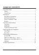
TABLE OF CONTENTS About This Guide................................................................................. 1 Purpose ............................................................................................ 1 Terms/Usage .................................................................................... 1 Introduction.......................................................................................... 2 Fast Ethernet Technology ..............................................................
ABOUT THIS GUIDE Congratulations on your purchase of the D-Link DES-1008P, an 8Port 10/100Mbps Fast Ethernet Switch with 4-Port PoE. This Switch integrates 100Mbps Fast Ethernet and 10Mbps Ethernet network capabilities in a highly flexible package. Port-1 to Port-4 on the switch support Power over Ethernet (PoE), meaning it will automatically detect the presence of an IEEE 802.3af-compliant powered device (PD) and provide power through the port. The switch provides up to 15.
INTRODUCTION This chapter describes the features of the D-Link DES-1008P Fast Ethernet PoE Switch and some background information about Ethernet/Fast Ethernet, Switching and Power over Ethernet technology. Fast Ethernet Technology The growing importance of LANs and the increasing complexity of desktop computing applications are fueling the need for high performance networks. A number of high-speed LAN technologies have been proposed to provide greater bandwidth and improve client/server response times.
Switching Technology Another approach to pushing beyond the limits of Ethernet technology is the development of switching technology. A switch bridges Ethernet packets at the MAC address level of the Ethernet protocol transmitting among connected Ethernet or Fast Ethernet LAN segments. Switching is a cost-effective way of increasing the total network capacity available to users on a local area network.
Power over Ethernet (PoE) Power over Ethernet (PoE) integrates power and data onto one single cabling infrastructure, eliminating the need to have AC power available at all locations. Power and Data is integrated onto the same cable, supporting category 5/5e up to 100 Meters. PoE will provide power to PoE compatible devices, such as IP telephones, wireless LAN access points and IP security cameras.
UNPACKING AND INSTALLATION This chapter provides unpacking and installation information for the Switch. Unpacking Open the shipping cartons of the Switch and carefully unpack its contents. The carton should contain the following items: One DES-1008P One DC power adapter Four rubber feet CD-ROM with Product Document Quick Installation Guide. If any item is found missing or damaged, please contact your local reseller for replacement.
Connecting Network Cable The Switch support 8 10/100Mbps Ethernet ports and Port 1 ~ port 4 are PoE Enabled ports, these PoE port will automatically activate when a compatible terminal is identified. The Switch will supply power through the Ethernet port to the connected PoE powered device (PD). For legacy devices that are not compatible, the PoE port will not offer power to this device. This feature allows users to freely and safely mix legacy and Power over LAN compatible devices on their network.
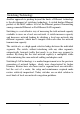
IDENTIFYING EXTERNAL COMPONENTS This chapter describes the front panel, rear panel, and LED indicators of the Switch. Front Panel The figure below shows the front panels of the Switch. Figure 1. Front panel LED Indicator: Comprehensive LED indicators display the status of the switch and the network (see the LED Indicators chapter below). Rear Panel Figure 2.
automatically detect the settings of the device and adjust itself accordingly. PoE Ports (Port 1~4 only): These ports are PoE Enabled ports, the PoE port will automatically activate when a compatible terminal is identified. The Switch will supply power through the Ethernet port to the connected PoE device. For legacy devices that are not compatible, the PoE port will not offer the power to this device. This feature allows users to freely and safely mix legacy and PoE compatible devices on the network.
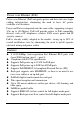
UNDERSTANDING LED INDICATORS The front panel LEDs provides instant status feedback, and helps monitor and troubleshoot when needed. Figure 3. LED indicators of the Switch System LED PWR: (Power Indicator) On : Power On Off : Power Off PoE status LEDs (Port 1 ~ Port 4) PoE Status: Green : When the PoE powered device (PD) is connected and the port supplies power successfully. When the PoE port has failed, possibly due to: Red : 9 9 9 Off : No PoE powered device (PD) connected.
PoE MAX At least 10W of PoE power is available to connect another PoE device. Off : Green When the power output to powered devices has reached or exceeded : the maximum power budget. No additional powered devices connected will be powered. Blinking Green Indicates at least 10W of PoE power is available again. Ethernet port status LEDs (Ports 1~8) 10/100M Link/ACT: 10M When the 10M LED lights on, the respective port is successfully connected to 10M Ethernet network.
For example: There are PoE PDs connected to the PoE Switch and the total power consumption is 48 watts. The system will reserve 8 watts for a buffer and the PoE MAX LED will light up. Once there is another PoE PD inserted, the system will not provide power to the additional PoE PD. Priority: This function will help protect the system when the system power is overloaded. The system will disable the PoE function of lower priority PoE ports to maintain the power to higher priority PoE ports.
TECHNICAL SPECIFICATIONS General Standards IEEE 802.3 10BASE-T Ethernet IEEE 802.3u 100BASE-TX Fast Ethernet IEEE 802.3x Full Duplex Flow Control IEEE 802.3af Power over Ethernet Protocol CSMA/CD Data Transfer Rate Ethernet: 10Mbps (half duplex), 20Mbps (full-duplex) Fast Ethernet: 100Mbps (half duplex), 200Mbps (full-duplex) Topology Star Network Cables 10BASET: 2-pair UTP Cat. 3, 4, 5; up to 100m 100BASE-TX: 2-pair UTP Cat.
Performance RAM Buffer: 96K bytes per device Filtering Address Table: 1K entries per device Packet Filtering/Forwarding Rate: 10Mbps Ethernet: 14,880/pps 100Mbps Fast Ethernet: 148,800/pps MAC Address Learning: Automatic update Transmits Method: Store-and-forward 13