DWL-P1012 12-Port Web-Smart IEEE 802.3af Power over Ethernet Midspan Version 1.
TABLE OF CONTENTS About This Guide ...............................................................................................1 Terms...........................................................................................................1 Overview of this User’s Guide...................................................................1 Introduction........................................................................................................1 Features..........................................
Discovery List ...........................................................................................13 Monitor List ...............................................................................................14 Device Setting...........................................................................................15 Toolbar ......................................................................................................16 Configuring the DWL-P1012 .............................................
A BOUT T HIS G UIDE This user’s guide provides instructions and information to aid in the installation of the DWL-P1012, most importantly how to connect the device to your network. Terms For simplicity, this documentation uses the terms “the Midspan” to refer to the DWL-P1012, and “Midspan” to refer to all Midspan Products, including the DWL-P1012. Overview of this User’s Guide Introduction Describes the Midspan and its features.
Features The DWL-P1012 features include: IEEE 802.3af Power over Ethernet compliant. Provides LED indicator for System and PoE status. Eliminates the need for AC outlets, local UPS and AC/DC adapters Web based Management for System and PoE power management. Supports SNMP protocol version 1 MIB support for: RFC1213 MIB II. RFC3621 Power over Ethernet MIB Private MIB. Independent overload and short-circuit protection per channel Standard 19-inch rack mountable.
U NPACKING AND I NSTALLATION This chapter provides unpacking and installation information for the DWL-P1012. Unpacking Open the shipping carton of the DWL-P1012 and carefully unpack its contents.
Setup Setup of the DWL-P1012 can be completed easily by following these steps: Install the Midspan on a sturdy, level surface that can support at least 6.6 lb. (3 kg) of weight. Do not place heavy objects on the device. The power outlet should be within 1.82 meters (6 feet) of the device. Visually inspect the power cord and see that it is fully secured to the AC power port. Make sure that there is proper heat dissipation from and adequate ventilation around the Midspan.
Installing the DWL-P1012 on a Rack The DWL-P1012 can be mounted in a standard 19" rack. Use the following diagrams to guide you. Fasten the mounting brackets to the DWL-P1012 using the screws provided. With the brackets attached securely, you can mount the DWL-P1012 in a standard rack as shown on the following page.
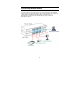
Connecting Network Cables As shown below, the Midspan is connected in series to an Ethernet switch/hub. The data outputs from the switch are connected to the Midspan. The Midspan delivers power over spare twisted pairs (pins 7/8 and pins 4/5) of the Category 5 cabling, without degrading the quality of data communications. The Management port may be connected directly or through a LAN to the Management station.
Each data port is configured as shown below, as data route-through ports for all data pins (pins 1, 2, 3 and 6). Be certain to use Category 5 or higher cabling to ensure proper operation. This PoE Midspan is not compatible with Gigabit Ethernet, any Gigabit Ethernet Capable device will only link at 100Mbps Full Duplex when connected to the DWL-P1012. IEEE 802.3af compliant Power Source Equipment will not energize the unused pairs unless an 802.
I DENTIFYING E XTERNAL C OMPONENTS This chapter describes the front panel, rear panel and LED indicators of the DWL-P1012. Front Panel Components The front panel of the DWL-P1012 consists of twelve (12) 10/100Mbps Fast Ethernet data ports (data only), twelve (12) 10/100Mbps Fast Ethernet PoE ports (data + DC power), one (1) 10/100Mbps Ethernet/Fast Ethernet port for out of band management and a Reset button. Data port (upper row of ports): Twelve 10/100Mbps Fast Ethernet data ports.
Rear Panel The rear panel of the DWL-P1012 contains an AC power connector. The AC power connector is a standard three-pronged connector that supports the AC power cord. Plug in the female connector of the provided power cord into this socket, and the male side of the cord into a power outlet. The DWL-P1012 automatically adjusts its power setting to any supply voltage in the range from 100 ~ 240 VAC at 50 ~ 60 Hz.
LED Indicators The LED indicators of the DWL-P1012 include Power, CPU, PoE status and Management port status. Refer to the appropriate section below for information on LED function and indication. System LED Power (PWR) On (green) : This LED will light green after the Midspan is powered on to indicate the ready state of the device. Off : When the Midspan is powered off or the power cord has an improper connection. Power Maximum (PWR MAX) On Off : When the PoE remaining system power <= 15.
PoE Port Status LED PoE Status Green Red Off : When a PoE powered device (PD) is connected and the port is supplying power normally. : When the PoE port fails in the following manner: PoE power circuit shortage. Power over current: over the power current of PD’s classification. Out of PoE voltage of 44 ~ 57 VDC output. Cost fail. : No PoE powered device (PD) connected or device is unplugged from the PoE output port.
C ONFIGURATION Through the Web Browser you can configure the DWL-P1012’s PoE power management configuration. With the attached Web Management Utility, you can easily discover all DWLP1012 units on the network, assign them IP Addresses, change the administrative passwords and upgrade firmware. Installing the Web Management Utility Follow these instructions to install and use the Web Management utility. 1. Insert the DWL-P1012 Master CD in the CD-Rom Drive. 2. Allow the CD to Autorun.
Discovery List This is the list where you can discover all the Web management devices on the network. By pressing the “Discovery” button, you initiate the discovery process which will find any available Web Smart devices connected to the same LAN as the PC running the Utility and list them. Double click or press the “Add to monitor list” button to transfer a device from the Discovery List to the Monitor List. System Term definitions in the Discovery List: MAC Address: Shows the device MAC Address.
Monitor List All Web Smart Devices in the Monitor List can be monitored; you can also receive SNMP traps and show the status of each device. System word definitions in the Monitor List: S: Shows the system symbol of the Web-Smart device, represent for device system is not active. IP Address: Shows the current IP address of the device. MAC Address: Shows the device MAC Address. Protocol version: Shows the version of the Utility protocol. Product Name: Shows the device product name.
The symbol “ ” represents a new trap signal has arisen, this symbol will disappear after you review and click on the event record. Add Item: To add a device to the Monitor List manually, enter the IP Address of the device that you want to monitor. Delete Item: To delete the device in the Monitor List. Note: In order to receive Trap information using the utility, the DWL-P1012 has to be configured with the appropriate Trap IP and Trap Events first.
Password Change: You can use the Password Change dialog when you need to change the password. Fill in the new and old passwords and press “Set” button to apply the password change immediately. Firmware Upgrade: If D-Link releases firmware to support new functions, the new firmware can be uploaded through here. Web Access: Double click the device in the Monitor List or select a device in the Monitor List and press the “Web Access” button to access the device through a Web browser.
In the “File TAB”, the choices are Monitor Save, Monitor Save As, Monitor Load and Exit. Monitor Save: To record the setting of the Monitor List to the default, when you open the Web Management Utility next time, it will auto load the default recorded setting. Monitor Save As: To record the setting of the Monitor List in appointed filename and file path. Monitor Load: To manually load the setting file of the Monitor List. Exit: To exit the Web Management Utility.
set on the same IP network. For example, the default IP address of the DWLP1012 is 192.168.0.1, so the manager PC should be set at 192.168.0.x (where x is a number between 2 and 254), and the default subnet mask is 255.255.255.0. Open a Java-enabled Web Browser, preferably Internet Explorer 6.0 or above. Enter the DWL-P1012 IP address http://192.168.0.1 (the factory-default IP address setting) in the address bar location.
19
Setup Menu When the main page appears, locate the Setup menu on the left side of the screen (see Below). Click on the setup item that you want to configure or monitor. There are eight options: SNMP, PoE, Schedule, Port Group, SNTP, Status, System, RTC Time, Trap, Password, Backup Settings and Reset Settings as shown in the Main Menu screen.
SNMP Setting Simple Network Management Protocol (SNMP) is an OSI Layer 7 (Application Layer) designed specifically for managing and monitoring network devices. SNMP enables network management stations to read and modify the settings of gateways, routers, switches, and other network devices. Use SNMP to configure the DWL-P1012 features for proper operation, monitor and detect potential problems in the DWL-P1012, switch, switch group or network.
MIBs Management and counter information are stored by the Midspan in the Management Information Base (MIB). The DWL-P1012 uses the standard MIBII Management Information Base module and Power over Ethernet MIB (RFC3621). Consequently, values for MIB objects can be retrieved from any SNMP-based network management software. In addition, the DWL-P1012 also supports its own proprietary enterprise MIB as an extended Management Information Base.
Delete Group: To delete a previously defined SNMP Community group, press “Delete Group” button, the Delete SNMP Community configuration window will pop out; check the delete dialog box. Press “Apply” to delete the selected SNMP Community Group. Modify Group: To modify a previously defined SNMP Community group, click on the ID parameter to enter to the selected SNMP Community Group and configure its community name and community enable. Press “Apply” to save the changes to the SNMP Community Group.
System Events: Monitoring the system’s status. Device Bootup: a trap when booting up the system. Illegal Login: a trap when an incorrect password is use in a login attempt. The IP address of the source will be recorded. PoE Events: Monitoring the PoE ports status. PoE Power fail: a trap when the port’s power source is fail. Power on/Power off: a trap when the PoE port’s power is on and down. Power over current: a trap when the PoE port’s power is over current.
Modify Trap: To modify a previously defined SNMP Trap, click on the ID parameter to enter the selected SNMP Trap to configure its community name, IP address and events. Press “Apply” to save changes. PoE Setting The PoE Setting screen shows the status of all PoE ports including PoE Enable, Power limit, Power current (Watt.), Power Voltage (V), Power current (mA.), Classification, Status, System budget power, Support total power, Remainder Power, The ratio of system power supply.
POE Port Status: Select “POE Port Status” to configure the PoE Port setting. To configure the settings, select a value from the drop down box corresponding to each feature. Poe Enable: Select to enable or disable the PoE function. Power limit: This function allows one to manually set a port power current limitation to be given to the PD, to protect the DWL-P1012 and the connected device, the power limit function will disable the PoE function of the port when the power is over loaded.
POE System Setting: Select “POE System Setting” to configure the PoE System setting. System power Threshold: When the percentage of power being supplied is greater than or equal to the System Power Threshold, the DWL-P1012 will issue an SNMP trap to alert the administrator.
To add a schedule profile simply click the Add button and define the parameters of the desired schedule. To modify an existing schedule profile click on the ID number next to the schedule profile to be modified. Name: Enter a friendly name for the schedule to be defined. Active Type: Select ‘Time Setting’ to define a begin and end date to the schedule profile. Select ‘Always Active’ to configure the schedule profile without begin and end date restrictions.
Port Group The advanced scheduling features of the DWL-P1012 rely on a port grouping mechanism that allows one to define groups of PoE ports. These groups are then assigned to a specific schedule profile which all members of that group adhere to. The default group cannot be modified or deleted and is assigned to the ‘Always Active’ schedule profile. Up to 6 custom groups may be defined each with its own corresponding schedule profile.
Click ‘Delete Group’ to remove an entire group. Select the check box next to the group to be deleted and click ‘Apply’ to remove.
SNTP The DWL-P1012 is capable of updating the system time using the Simple Network Time Protocol. When a valid DNS Server address is configured the DWL-P1012 can resolve DNS names for time servers prior to synchronization. From the SNTP configuration page of the Web UI, select SNTP Server Setting to manage the list of NTP servers used to synchronize. Select SNTP Time Zone & DST to configure the Time Zone the midspan is located in and enable Daylight Savings Time if desired.
Device Status Click on the “Status” hyperlink to display the device status on this screen, it will show the System Status, SNMP Settings, PoE Status, Schedule Profiles, Port Grouping, SNTP Server and Daylight Savings Time info. This page will load upon a successful login to the WebUI.
PoE Status Schedule Profiles Port Group SNTP Server 33
SNTP Time Zone and DST Press “Refresh” when you need to renew the posted information.
System Setting The System Setting includes the Web Server Port, System name, Location name, Login Timeout, IP Address, Subnet Mask, Gateway and DNS IP addresses. Through the Web Management Utility, you can easily recognize the device by using the System Name and the Location Name.
RTC Time The DWL-P1012 includes an integrated Real Time Clock to handle timekeeping duties in order for port scheduling to properly function. The time may be set using one of three methods: Manual Configuration, PC Time, and SNTP Synchronization. To manually configure the System Time select the year, month, and day from the appropriate drop down. Select the hour (in 24-hour notation), minute and second and click the ‘Set Time’ button to apply the changes.
To synchronize the DWL-P1012 with an NTP server to retrieve the current time and date select ‘SNTP Time’ from the drop down menu. The DWL-P1012 will then contact the first SNTP server in the time server list in a top-down order to update the system time. The correct time should appear in the appropriate fields. Click the ‘Set Time’ button to apply changes.
Trap Setting The Trap Setting enables the DWL-P1012 to monitor the selected Events through the Web Management Utility, configure the Trap IP Address of the manager where the trap should be sent. System Events: Monitoring the system’s Status. Device Bootup: a trap when booting up the system. Illegal Login: a trap when a wrong password is used in a login attempt. The IP address of the source will be recorded. PoE Events: Monitoring the PoE ports status.
Set Password A password is an invaluable tool for the manager to secure the management interface of the DWL-P1012, use this function to change the password. If you forget the password, press the “Reset” button in the front panel of the DWL-P1012 for 10-15 Seconds. All current settings such as Port Settings, SNMP, etc. will be lost and the DWL-P1012 will be restored to the factory default settings. Backup Setting The backup tools allow one to create backup files of current settings of the DWL-P1012.
Logout Clicking the logout Hyperlink will log you out of the web-based administrative interface. You will be redirected to the beginning log-in page.
WARRANTY Subject to the terms and conditions set forth herein, D-Link Systems, Inc. (“DLink”) provides this Limited warranty for its product only to the person or entity that originally purchased the product from: D-Link or its authorized reseller or distributor and Products purchased and delivered within the fifty states of the United States, the District of Columbia, U.S. Possessions or Protectorates, U.S. Military Installations, addresses with an APO or FPO.
Limited Software Warranty: D-Link warrants that the software portion of the product (“Software”) will substantially conform to D-Link’s then current functional specifications for the Software, as set forth in the applicable documentation, from the date of original retail purchase of the Software for a period of ninety (90) days (“Warranty Period”), provided that the Software is properly installed on approved hardware and operated as contemplated in its documentation.
The original product owner must obtain a Return Material Authorization (“RMA”) number from the Authorized D-Link Service Office and, if requested, provide written proof of purchase of the product (such as a copy of the dated purchase invoice for the product) before the warranty service is provided.
D-Link, the sellers, or the liquidators expressly disclaim their warranty obligation pertaining to the product. Repair by anyone other than D-Link or an Authorized D-Link Service Office will void this Warranty. Disclaimer of Other Warranties: EXCEPT FOR THE LIMITED WARRANTY SPECIFIED HEREIN, THE PRODUCT IS PROVIDED “AS-IS” WITHOUT ANY WARRANTY OF ANY KIND WHATSOEVER INCLUDING, WITHOUT LIMITATION, ANY WARRANTY OF MERCHANTABILITY, FITNESS FOR A PARTICULAR PURPOSE AND NON-INFRINGEMENT.
or consequential damages, or limitations on how long an implied warranty lasts, so the foregoing limitations and exclusions may not apply. This limited warranty provides specific legal rights and the product owner may also have other rights which vary from state to state. Trademarks: D-Link is a registered trademark of D-Link Systems, Inc. Other trademarks or registered trademarks are the property of their respective manufacturers or owners.
limits are designed to provide reasonable protection against harmful interference in an industrial installation. This equipment generates, uses, and can radiate radio frequency energy and, if not installed and used in accordance with the instructions, may cause harmful interference to radio communication. However, there is no guarantee that interference will not occur in a particular installation.
Technical Support You can find software updates and user documentation on the DLink website. D-Link provides free technical support for customers within the United States and within Canada for the duration of the warranty period on this product. U.S. and Canadian customers can contact D-Link technical support through our website, or by phone.